The Projection FOV is a user-friendly and configurable system designed for projecting textures onto a geometry. Useful for:
implementing areas of visibility in 3D games
projecting colorful textures on the environment
simulating shadow maps in toon shading systems
simplified fast cheap alternative for the spotlight
Features
camera field of view control combined with depth test
supports two types of material rendering (mesh-based and decal-based)
frustum area attachment debug
advanced coloring and texture mapping
cinema-like projector
multiple types of shape projection (rectangle, circle, masked)
can be attached to sockets and bones
configurable projection receivers
distance-based coloring
camera direction and game type independent
Gallery
Documentation
Getting Started
It’s good to start with an example demo that presets all features and a wide range of possibilities for implementing the system in the game.
The simplest way to use Projection FOV is:
Drag and drop BP_ProjectionFOV on the map.
Adjust the actor to your scene or attach it to the actor using (the AttachTo function)
Choose the material and set it to the ProjectionMaterial attribute. You can use any type of material from templates ProjectionFOV/Materials/Templates
Projection FOV
Two types of projection can be used with the Projection FOV system – decal projection and mesh projection. The type of projection is detected automatically based on the master material used in the blueprint. Both have some special features and some limitations that need to be addressed.
Decal projection
Implemented in master material M_ProjectionFOV_Decal
Can be only used with the BP_ProjectionFOV actor because requires a decal component.
Can be filtered by “Receive decals” so you can disable the rendering effect on some meshes.
Uses translucent blending
Good for rendering area of sight
Decal projection material used in the Projection FOV blueprint for presenting the area of visibility.
Mesh projection
Implemented in master material M_ProjectionFOV_Mesh
Works pretty well with normal fading
Can be used on static meshes (SM_FrustumInside or SM_Light)
Uses multiplication blending
Good for simulating spotlight (car lights)
Mesh projection material used in example car blueprint as multicolored spotlights.
Material parameters
The Projection FOV comes with predefined material instances (ProjectionFOV/Materials/Templates) configured for use in some specific cases.
Users can create their materials as well by creating a copy or material instance from master materials M_ProjectionFOV_Decal/M_ProjectionFOV_Mesh.
Material parameters can be also modified dynamically during gameplay ProjectionInstance in ProjectionFOV.
Changing the base color of projection in gameplay using material instance reference.
Infinity Weather update 1.1 is ready now! A full list of changes is available on Trello.
Solder is a short RTS style game concept placed in the futuristic science fiction world inside the computer on an imagined PC Board.
The tech demo is an introduction to basic RTS mechanics based on a parasite chip called SOLDER that evolves during the journey on PCB.
My newest package called “Infinity Weather” is available on the unreal marketplace now.
Infinity Weather is a powerful and clean system designed for weather control in Unreal Engine.
The package is a combination of 7 systems that could be divided into separate packages: wind, displacement, landscape, precipitation, footsteps, fog, and post-process now available as a configurable unified system.
Features
Displacement:
configurable displacement capture blueprint
top-down projection of displacements rendered using shape definition in the shader (sphere, capsule, box, cylinder, decal, trace-sphere)
skeletal mesh displacement supports
interface for easy integration with all types of actors
area of displacement moves dynamically with the actor or camera
time-based accumulation of snow
build functions can be used for multiple other effects (like grass interaction)
displacement material functions ( snow, mud, sand, grass)
small world texture (1024×1024) can handle even 150x150m area
Post-process:
two materials with fast dynamic switching between material permutations
Make sure that the Infinity Weather package version is up to date. The current newest version is described at the top of the documentation.
The package requires a Procedural Mesh Component and Sun Position Calculator to work so make sure that it’s enabled.
A new sky system requires a Sun Component
I’ve decided to make this project downloadable content that can be added to the project. Unreal Engine does not support sending config files in downloadable content so users have to add footsteps configuration in the project that uses pack to make it work properly. The process is really simple:
Open the project configuration Edit->Project Settings
Select tab Engine->Physics and scroll down
Add physical surface types: Snow, Sand, Mud, Rock
The package works perfectly with the TPP input config files. if you have used another template then probably you will have to add inputs into your project for package testing:
Every user of this package should start by checking all examples delivered with the product. Example maps can be found in the InfinityWeather/Demo/Maps folder.
There are available multiple examples that preset different configurations:
SnowMap – simple snow effects with lightweight landscape material.
RainMap – simple rain and mud effects with lightweight landscape material.
DesertMap – simple desert and sunny weather with lightweight landscape material.
WorldMap – advanced multi-layered material with mixed landscape effects.
The example character interaction with the Infinity Weather world is implemented in Demo/Mannequin/BP_DemoCharacter by four basic components added to it:
BP_InfinityFootstepComponent – spawns footsteps effect from notifiers
BP_InfinityDisplacementComponent – renders shapes for ground displacement
BP_InfinityPostProcessComponent – controls post-process and controller communication.
BP_InfinityPawnComponent – additional effects on a character like breath particle when it’s cold.
Weather Control
The most important element of the pack is the InfinityWeather/BP_InfinityWeatherController blueprint that gives the users the possibility to control weather conditions like fog, wind direction, precipitation, and accumulation.
Drag and drop BP_InfinityWeatherController on your level to start controlling the weather.
Default properties of the world weather can be set in the BP_InfinityWeatherController
Atmosphere effects requires Exponential Height Fog plugged into the BP_InfinityWeatherControllers to work properly. Remembet to polace height fog actor on your map and set the attribute of weather controller.
A list of weather controller attributes looks simple but it’s a very powerful tool. For testing try to set some rainy windy weather using parameters like the below:
The system can be controlled dynamically by blending between parameters during the game using the functions below.
Functions of weather controller implemented for controlling the weather dynamically.
Precipitation
The precipitation system is based on a Niagara particle system calculated on GPU only in camera space which makes it very efficient.
There are a few predefined effects of precipitation defined in the project (/InfinityWeather/Precipitation/)
Rain/BP_InfinityPrecipitationRain
Snow/BP_InfinityPrecipitationSnow
Dust/BP_InfinityPrecipitationDust
The precipitation effect can be used without a weather controller. You can drag and drop the blueprint of the chosen effect on the map to use it as static volume.
Rain and snow precipitation were placed on the map.
A manually placed actor can be configured and limited by the area of precipitation. Users also can set multiple weather types visible locally in some areas of the map. All parameters are described in editor hints.
You can create your own precipitation effect classes for specific rain/snow configuration by extending the base class and changing attributes. That newly created class will be available on the Precipitation Effect Class list in weather controller.
The /InfinityWeather/Precipitation/BP_InfinityPrecipitationOcclusion is a specific type of actor that contains a render target texture used for calculating precipitation collision with the roofs and other cached meshes. After placing this actor on the scene you will notice that in the area of the occlusion map the rain and snow are not rendered under the meshes.
The white box is the occluder. Occlusion map preview rendered over the mesh. Notice that there is no rain under the occluder.
Currently supported is only one occlusion map per level but its planned to implement switching between multiple occlusion maps dynamically.
Wind
The wind is based on the integration of multiple effects that react to a simple wind direction vector.
Currently, the wind effects can be controlled globally on the full scene using the Wind Direction vector in BP_InfinityWeatherController.
Most of the objects that react to wind use the Environment/Functions/MF_InfinityWind material function that returns all important information about the current wind status. It’s the simplest way to get global wind data.
List of implemented effects and objects that react to the wind force.
Precipitation direction – Attribute Wind Force in precipitation blueprint scales how much it affects
Vegetation – MF_WindBush, MF_WindTreeLeafs, MF_WindTreeTrunk, and MF_WindGrass nodes implement the effects of wind on vegetation.
Flags – specific implementation of flag material M_Flag.
Cascade particle emitters (Wind Affected Emitters attribute in Weather Controller is a list of emitters that should use Wind Direction and Wind Intensity parameters to react. (Example Environment/Dust/PS_SnowBlowingLarge)
Dust – predefined planar dust effects that rotate and fade based on wind direction.
Grass – MF_WindGrass material node.
Landscape dust – MF_GroundDust effect on the sandy landscape.
Clouds shadow – M_CloudsShadow
Fog
The BP_InfinityFog actor can be used for changing fog settings in some areas. Fog actor is divided into two parts
Fog volume – The volumetric shape of fog is rendered as overlay mesh.
Fog atmospherics – Atmospherics settings. When the camera is inside the Fog volume the controller uses those settings to blend into new parameters based on the Weight attribute value.
Currently supported is only the ellipsoidal shape of fog.
Accumulation
Accumulation is the group of parameters that controls the coverage of snow and wetness of meshes that uses the MF_InfinityWeatherSurface node in the master material.
MF_InfinityWeatherSurface is an advanced node that adjusts base color, normal, and roughness values to current weather conditions set by the two basic parameters that are used in the material.
Weather.Controller.WetSurface – Controls wetness of the surface
Weather.Controller.SnowySurface – Controls the snow shell on the surface.
An example of MF_InfinityWeatherSurface use is presented in the rocks material M_RockSnowMaterial. Drag and drop rocks mesh(/InfinityWeather/Demo/Environment/Rock/SM_Rock ) on your map to check how weather conditions affect the material. Notice that the combination of wetness and snowy material can result in a nice-looking effect of icy snow.
Left top: Wet Materials = 0.0, Snowy Materials = 1.0 Left bottom: Wet Materials = 0.0, Snowy Materials = 1.0 Right top: Wet Materials = 1.0, Snowy Materials = 0.0 Right bottom: Wet Materials = 1.0, Snowy Materials = 1.0
Additionally, meshes can be painted by vertex color (red channel) to mask the effect on meshes that are hidden under the occluders.
A more detailed description of additional parameters can be found in the landscape and displacement section.
Displacements
The Infinity Weather system introduces an advanced displacement material system based on render targets. In short, the BP_InfinityDisplacementCapture actor is searching for actors around the focus point, that implements BPI_DisplacementShape. BPI_DisplacementShape implementation adds the list of shapes (a type of shape and transform) to the stack. In the final stage stack of shapes is rendered to displacement texture. The iteration is repeated every frame with some random offset.
3 elements are needed to make the system work:
Displacement receiver landscape with the material that supports displacements. (MI_LandscapeSnow/MI_LandscapeMud/MI_LandscapeSand, MI_LandscapeCombined)
Displacement capture actor placed on the map (BP_InfinityDisplacementCapture), set to capture landscape ground.
Displacement mesh actor or component that will affect the ground (BP_InfinityDisplacementStaticMeshActor)
The video below shows how to combine all these tools and make them work:
Landscape materials
Landscape material is an advanced topic because requires basic knowledge about an unreal material system to inject them into the project.
Example content (Landscape/Materials) comes with a few examples of the landscape configurations to make this step easier. There are simple materials that cover the landscape fully with a single type of displacement:
M_LandscapeSnow (uses MF_InfinitySnow)
M_LandscapeMud (uses MF_InfinityMud)
M_LandscapeSand (uses MF_InfinitySand)
There is also an advanced version of the material that is a combination of all three effects in one landscape. Additionally, the extended version supports the MF_InfnityWeather. Available in two versions virtual texturing and multilayered
MI_LandscapeCombinedLayered
MI_LandscapeCombinedVirtual
Let’s take a look at the example Sand (M_LandscapeSand) material used on DesertMap:
The material is a combination of four nodes:
MF_GroundDand – it’s the base material layer of sand that contains a color map, normal map roughness, etc. It can be replaced by any material for example created from GameTextures/Example Project/Any pack.
MF_InfinityDisplacement – is a base node that reads displacement render target and returns data from it. As an input, it takes the displacement layer intensity. It’s the layer that will be used to paint the landscape.
MF_InfinitySand – combines data from displacement and ground layer. Additionally, this node implements some additional effects like coloring displaced ground. There are another two nodes that could be used here to achieve another effect MF_InfinityMud, and MF_InfinitySnow.
MF_InfinityWeather – adding the overlay effect of a wet surface that can be controlled by the weather controller.
Displacement capture
The BP_InfinityDisplacementCapture is the main actor that prepares displacement depth textures for the landscape. Below is a simple explanation of how the algorithm of this actor works:
Displacement capture actors are searching for actors that overlap the area of displacement.
If an actor that supports the displacement interface is detected then he is asked about list shapes to displace ground.
New generated shapes are added to the stack.
In the final step, the displacement capture actor renders all shapes added to the stack.
A simple configuration of the scene with displacements is presented below:
Drag and drop BP_InfinityDisplacementCapture on the map.
Add the Landscapeactor to BP_InfinityDisplacementCapture.GroundMeshes.
it’s an important step to notify the system about the receiver of the displacements.
Select landscape and use the material that supports displacements for example M_LandscapeSand.
Edit the landscape and paint the layer of displacement on it.
For optimization, displacements are rendered only in the area of the focus point. The focus point is taken from BP_InfinityDisplacementCapture.CaptureActor. If the CaptureActor is null then it uses the character Pawn as the focus. If Pawn is null then it uses camera location.
Two types of render targets are defined in the system. Both area sizes can be changed in the capture displacement actors.
Capture Render Target – cache shapes around the focus point. Modify the CatureTextureSize attribute.
World Render Target – combines all cached data. Modify the render target TR_Persistent.resolution to adjust the size of history.
Simple static shapes
The displacement map rendering is based on ray tracing shapes in the shader to get the best possible efficiency but it’s also limited to the number of shapes predefined in shaders. The shapes that can displace the ground are defined in the /InfinityWeather/Displacement/Blueprints/Shapes/ folder:
BP_DisplacementStaticMeshCapsule
BP_DisplacementStaticMeshCube
BP_DisplacementStaticMeshCylinder
BP_DisplacementStaticMeshSphere
BP_DisplacementDecal (heightmap mapping on the ground)
All of them can be placed on the map and scaled.
Use Debug Option in BP_InfinityDisplacementCapture to preview shapes that are rendered by capture displacement
Character displacement
BP_InfinityDisplacementComponent is a component that allows attaching a list of shapes that affect displacement ground.
The example implementation of the displacement component in a clean mannequin character is presented in the video below:
Adding displacements to your character is easy:
Open the character blueprint, and add BP_InfinityDisplacementComponent to your character.
Select the component and set the Displacement Shapes data asset. You can use full ragdoll (DS_MannequinRagdoll) or foot (DS_MannequinFoots) implementation that is faster and more prepared for walking.
Select “Class Settings” on the top bar and add the BPI_DisplacementShape interface to the list of Implemented Interfaces. It should look as on the screen:
Now implement the interface function called AddDisplacementShapeData.
After those few steps, the character will be detected and ready to work.
Custom collision
The Infinity Weather displacement capture system uses box collision volume during searching for the actors that should be captured in the displacement buffer. The overlap detection requires a specific collision type for filtering collision shapes. The engine has no option to include a custom collision type in the external marketplace package because it’s defined in the configuration files.
By default, Infinity Weather takes advantage of using a predefined destructible collision type but it’s not the best solution for every project, this collision type can be occupied by other functionalities and turned off for specific actors like characters.
The best way to overcome this problem and also improve performance during overlap tests is by creating a custom collision type and using it to detect shapes that should be detected in the displacement area This solution will also fix all issues with ALS ragdoll detection and other strange behaviors that could occur after placing BP_InfinityDisplacement actor on the map.
Creating a custom collision type is described in the Unreal Engine 4 documentation and the explanation below shows how to apply this knowledge with Infinity Weather:
1. Find Edit->ProcectSettings->Collision
2. Open the ObjectChannels tab and add a New Object Channel type called “InfinityCapture“, set to ignore by default.
Adding custom collision type.
Now you have to set a new collision type in the displacement capture actor.
It’s good practice to inherit BP_DisplacementCapture class and edit the child class instead of changing package assets. If you do tit this way then the next package update will not break your project.
Open BP_DisplacementCapture (or child instance) and find the CaptureVolume component.
In CaptureVolume->DetailPanel->Collision->CollisionPresets->ObjectType set the InfinityCapture type.
Object type set to Infinity Capture in displacement capture actor.
Since now every actor that has set Collision Response->InfinityCapture->Overlap true will be considered during the displacement detection process.
Find the character class and select the collision component that should be detected (CapsuleComponent or Mesh)
In the details panel find the Collision tab -> Collision presets
If the collision preset type is “Custom…” then just switch InfinityCapture->Overlap to true.
Otherwise, you will have to set custom or edit existing presets the same way in project collision settings. Infinity Capture Overlap set to true in a captured actor (Pawn or shape).
Remember to repeat these steps for all actors that should be detected by displacement capture like BP_InfinityDisplacementStaticMeshActor.
You can use debug option in BP_InfinityDisplacement actior to see if the actor is detected.
Displacement data asset
The configuration of displacement shapes attached to actors is stored in Data assets (PDS_DisplacementShapes).
The Infinity Weather contains a few examples of data assets for mannequins and vehicles but any user can create custom data assets that will work with specific skeletal mesh. Creating a displacement data asset is simple:
Press the right mouse button in the content browser
Select Miscellaneous->DataAsset
Pick PDS_DisplacementShapes and create
Set the name of the newly created data asset “DS_ExampleDataAsset” for future use.
Newly created data assets can be used in the characters but we still need some shape definitions. Shapes can be added by hand but Infinity Weather comes with a simple editor that helps preview how shapes are attached.
Displacement shapes editor. Ragdoll is in edit mode.
Drag and drop the editor class on the map (BPU_InfinityDisplacementShapesEditor).
Select editor, and chose newly created data assed (DS_ExampleDataAsset) in Data attribute.
Pick the skeletal/static mesh reference that will be a visual representation of the shape that makes displacement. It can be your character or car.
Press Load and now you can add shapes to the List. The shape structure is described below.
After work is done press the save changes using button. Remember to apply the newly created data asset in DisplacementComponent.
Shape property
Description
Socket
Bone or socket name used as an attachment transform. The system will use component transform if the socket name is not defined.
Shape.Type
Shape type. Currently supported: Box/Sphere/Cylinder/Capsule/Decal, Trail Wheel, Trail Sphere
Shape.Intensity
Scale the intensity of interaction (not implemented yet)
Shape.Transform
Relative transform in space of attachment.
Shape.Pattern
The texture is used as a pattern in the displacement decal.
Footsteps
Weather System also supports the advanced footstep system integration based on notifiers placed in animation.
Working with footstep system:
Add BP_InfinityFootstepComponent component to a character. The configuration of components contains default predefined templates of effects and attachments for the mannequin.
Add BP_NotifyFootstep to the animation of walking/running in place when the foot hits the ground. Choose the left or right foot in the properties.
Add BP_FootstepVolume on your scene and select the preset of footstep that should be spawned inside of the volume.
Footstep volume
The engine sometimes wrongly detects the footstep ground because of limited landscape layers blending during ground tracing. Footstep volumes BP_FootstepVolume can solve this problem easily. When the character is inside the volume then the system uses the footstep set in the volume definition so the incorrect footstep effect is overridden.
The priority and Required conditions are taken into account to choose the most relevant footstep effect. It can be even filtered. The example below shows how to config volume on second priority (higher priority more important) that spawns snow and will be visible only when there is at least 0.1% of the weather displacement active.
Screen Effects
The BP_InfinityPostProcessComponent placed into an actor that contains the camera component will add automatically the post-process material and communicate with the weather controller to get info about the current conditions.
Three types of post-process view objects are supported:
Postprocess camera – by default system searches for the camera in owner.
Postporcess component – if there is no camera in the owner then the system searches for a component.
Postprocess Volume – custom volume can be set for the character on the scene by setting the Postprocess volume attribute.
A custom post-process object can be also set by the function SetPostProcessView.
Features:
Raindrops and circles show only when the precipitation actor has IneractWeather > 0.0. That means raindrop shows only inside the rain volume.
Screen raindrops fade after some time. The duration of the fade can be controlled by BP_InfinityPostProcessComponent.Rain parameters.
When the camera is under the cover it’s not getting wet and raindrops are not appearing.
Freezing and heat haze distortion are calculated locally from the weather controller and fog actor’s atmosphere. (temperature, distortion)
Raindrops post-process. The effect is activated when the weather is rainy.
The screen effects are implemented using two post-process materials.
MI_InfinityPreTranslucent – a group of effects rendered before the translucency layer.
Rain Circles – Enables automatically when rain precipitation is active.
Distortion – Heat Haze effect that enables when
Glittering – Experimental disabled effect of glittering rendered on snow and sand.
MI_InfinityPostProcess – a group of effects rendered after the tone-mapping.
Sharpening – Additional sharpening effect that improves the quality of close objects (can be disabled) by UseSharpening.
Drops – Animated raindrops on-screen are visible only if the camera is exposed to rain.
Frozen – Frozen screen edges.
Replication
The replication of the weather is implemented on the server side. That means all functions from BP_InfinityWeatherController that control weather should be activated on the server and then the state will be automatically sent to clients. The state of the weather is also replicated when the player joins to game after some time.
Displacement render targets are not replicated but only calculated locally around the focus point of the displacement capture actor that follows the local player 0. That means if multiple actors are walking in the same area at the same time then the result will be calculated locally and similar for all of them. It behaves this way not because it’s replicated but because it’s simulated locally with the same data.
Two players connected in a multiplayer game and displacements.
During testing displacements in multiplayer be sure to run it in separate instances of the game, otherwise, UE4 shares the memory of ground texture and there are bugs because multiple displacement actors render the same displacement texture at the same. This issue does not affect the final released game so don’t worry. Use option SingleProcess=false for testing the game in the editor with proper displacements in multiple windows.
Testing multiplayer setup.
Future features that will be implemented for multiplayer games:
Local weather controllers are not supported yet but it’s something on my roadmap.
Replicated foodprint decals that will be sent to clients and activated when displacement actors close.
Sky System
The Infinity Weather 2.0 introduces a completely new sky system which is simultaneously the most innovative feature of this product.
The sky is organized out of a few separate blueprints responsible for different parts of the sky rendering:
BP_InfinitySky is the basic class that manages fundamental sky-related settings, providing the flexibility to customize visual appearance. The system links useful components that can be adjusted:
atmosphere
exponential height fog
background clouds
celestials (Sun, Moon, and stars)
post-process exposure
Skylight
After adding an actor map map system works automatically, and you can edit all parameters according to the descriptions highlighted when the mouse is hovering over it.
By default, the BP_InfinitySky system uses the SunRotation attribute to control the position sun in the sky. It’s a simple solution that gives 100% control but is not very handy when you want to build a real world which is why the BP_InfinitySolarSystem actor was created.
BP_InfinitySolarSystem – The solar system is an actor that feeds the Sky with information about the celestials based on the current time, date, and localization to calculate the Sun position. Configuration is simple:
Add BP_InfinitySolarSystem on your level
Select BP_InfinitySky andset BP_InfinitySky.SoilarSystem = (the solar system added before)
From now SunRotation will be calculated using SolarSystem configuration and you can use BP_InfinitySolarSystem.TimeOfDay parameter to control the sun position.
It requires the build-in engine Sun Position Calculator plugin to work properly otherwise blueprint won’t compile, so make sure the plugin is enabled in your project:
BP_InfinityLightning – It involves generating the effect of illuminating clouds at the location of lightning. It randomizes lightning within a specified area, allowing for periodic activation, and also displays lightning bolts.
Additionally system provides the BP_InfinityLightningMask actor which defines a mask area that can be used for cutting off the light effect inside the buildings. The example of use is presented on the RainMap.
It seems like an emissive output is doing the job. I love the way volumetric clouds work in #UnrealEngine. The lightning bolt effect is from my Lightning Fast asset.
BTW, the Infinity Weather update is ready and awaiting approval! 🙂 pic.twitter.com/zC13LiqNDF
BP_InfinityVolumetricClouds – Separate volumetric clouds system that can be easily integrated with every project without destroying other lightning settings on the map.Shipped with 20 predefined cloud presets that can be easily mixed. The volumetric cloud control is simplified to a few basic parameters (Coverage, Slope, Density, Erode, Softness, Light) that can model many different types of clouds.
The system supports two data assets of clouds Primary and Secondary that are blended partially by a defined circular area. The area of blending is defined by three parameters.
SecondaryCloudsPosition – Position of center (represented by the 3D point that can be moved in the editor)
SecontaryCloudsRadius – Radius of the circle area
SecontaryCloudsSoftness – Softness of the circle area
When PrimaryDataAsset/SecondayDataAsset are not specified system automatically uses the parameters PrimaryClouds/SecondaryClouds so there is no need to build data asset for every sky setup.
The BP_InfinityVolumetricClouds system can also cast high-quality shadows on the ground. The feature is implemented using a light function whitch means it requires changing parameters in Direcitonal light used by the system as the Sun. It can be done by using TargetSunLightActor, you can use BP_InfinitySky, DIrectionalLight, or even UDS sky as a target.
EUW_InfinityCloudsEditor – The volumetric cloud editor enables the blending of sample presets and the creation of new ones.
The tool is simple to use:
Find EUW_InfinityCloudsEditor in content.
Click right on EUW_InfinityCloudsEditor and choose Run
Select the BP_InfinityVolumetricClouds
Duplicate some of the existing cloud data assets
Choose the duplicated cloud data asset in EditedDataAset of editor the data asset to edit
Use cloud parameters or a mixer
Use “Save Asset” button to write into EditedDataAsset
It definitely took me too long, but I finally found the ‘right’ parameters for volumetric clouds. The Infinity Weather update, which will also include support for UE5, is coming soon 🙂 pic.twitter.com/PI0P99oxwt
The integration with the Sequencer allows for cloud control through a timeline with the ability to scroll through time and adjust cloud transition effects.
I’ve successfully gained control over the sky in the sequencer. The configuration could be more intuitive but it’s still better than nothing. 🙂 #UnrealEnginepic.twitter.com/2sCVD9V9QY
The most important part is implementing a custom collision type that will solve most of the problems related to ALS and IW volume overlapping. You can find detailed descriptions of this step in the chapter called “Custom Collision Type”.
After you finish this collision configuration then additionally it is worth setting Climbable = Ignored in Trace Responses of Capture volume component because it’s not needed. The final configuration of the InfinityCapture actor should look like below:
It’s also important to update the ALS_Character collision preset in the project config. The InfinityCapture channel should be set to overlap.
Ragdoll
When the collision setup is ready then it’s time for ragdoll. During ALS ragdoll mode capsule overlap is not detected and that is why displacements are not rendered by default. There are two possible methods to fix it and the choice on you:
Select ALS Character Mesh and switch Generate Overlap Events = true, and InfinityCapture channel to Overlap.
Alternative more general method. ALS_Character -> Add Component ->Sphere Collision to character actor and configure attributes as presented on the screen below:
There is another important thing about ragdolls that is switching between presets ragdoll/feet.
The DS_MannequinRagdoll preset is slower and more precise, the DS_MannequinFoots preset works perfectly in low FPS because it supports continuous movement. Fortunately, ALS can support this feature very easily ALS_AnimMan_CharacterBP has functions RagdollStart and RagdollEnd that perfectly fit the requirements of switching.
Use SetDisplacementShapesDataAsset on the DisplacementComponent.
RagdollStart should set DS_MannequinRagdoll asset as a parameter
RagdollEndshould set DS_MannequinFoots asset as a parameter
Questions & Answers
I can’t see any precipitations under the 0.0 of the level.
Add BP_InfinityPrecipitationOcclusion on your map.
Explanation: The system by default reads 0.0 as the default occluder. BP_InfinityPrecipitationOcclusion will analyze your level occlusion and update the height of the ground.
Why landscape is flickering after painting the displacement
Solution: Use a geometry brush on the landscape to displace mesh a bit and mesh will not disappear anymore.
Explanation: It's an engine bug, that I can't overcome but it's easy to fix in your project. The only way to fix this is to increase the size of the landscape component bound box by editing the ground. The bug is related to the bounding box of landscape fragments. If landscape bounds are hidden under displacement mesh (extruded using vertex offset|) then the occlusion system removes the fragment of landscape. It flickers because the occlusion is probably calculated based on the previous frame and in the previous frame, the component visibility was the opposite.
I am very happy to introduce my new game demo created especially for the NVIDIA spotlight contest.
Lightning Fast is a powerful combination of materials and blueprints that implements a wide range of realistic and stylized electricity effects.
Lightning effects have plenty of uses in games, from background ambiance during a storm, and electric fences to devastating lightning guns and spells. This system is designed in mind to achieve all those effects with high performance, and AAA quality at the same time.
Two types o beam rendering (spline mesh/spline billboard mesh)
Integrated with UE4 dynamic lights and material light functions and splines
Over a hundred parameters in materials to customize the final effect
Spline spline-based shape of the bolt easy to adjust to the scene
Character electrocute discharges effect
Advanced lightning mesh editor tools
Multiple animated lines rendered in a single beam
Depth fade/direction fade effect
Glow and line color
Refraction based distortion
Procedural beam texture
Dynamic branch masking and fading effect
Additional content:
prototype pack – textures and materials created for demonstration purposes
mesh generator – an advanced tool prepared for editing and generating lightning meshes, allows implementing external lightning propagation class
demo example map – a showcase of 14 use cases
Procedural mesh lib – Additional library of functions that helps to create static meshes in UE4
Gallery
Documentation
Getting started
Everything starts from the geometry (meshes) and effect(materials) rendered using geometry.
The Lightning Fast mesh combined with the material has some useful features and properties that are very important in production.
can be used with spline meshes
can be skinned and used as skeletal mesh
can be scaled and keeps the proper shape
can be used in a particle system
can be watched from every angle
That gives us a wide range of effects that the system can handle so the package is divided into multiple blueprints specialized in custom effects.
All of the effects can be found in the Blueprint folder and are presented on ExmapleMap (Demo/Maps/LightningFastMap)
Example use-case:
Find folder Blueprints/LightningBolt
Drag end drop BP_LightningBolt on scene
The effect is ready to use. Now you can adjust parameters to get the effect that you need.
Blueprints
Blueprints folder contains multiple lightning effects that show how the system works with materials and meshes is should be treated as example content or templates prepared for general use cases. Some of the effects contain blueprints the others are represented only by particle effects that the main character is using.
Check the Demo/Mannequin/ThirdPersonCharacter blueprint to analyze the implementation of the skills.
The list of effects will be extended in future updates.
It’s good practice to create your own effects by inheriting Blueprint classes and copy material instances to your project folder.
Lightning Spline
The Blueprints/BP_LightningSpline blueprint is a simple combination of mesh spline effects and lights. You can combine any mesh created using the Lightning Fast package with splines even bending the lightning bolts is allowed.
Drag and drop BP_LightningSpline on the scene and modify parameters. [Editing splines]
Mesh
Description
Static Mesh
Mesh used to bend
Material
The material used in mesh
Forward Axis
The axis of the mesh is directed forward of bending.
Translucency Sort Priority
Rendering priority
Fix Spline Direction
Additional correction of spline UP direction. Fixes some twist bugs.
Texture Scale
Scale texture UV for beam start and end.
Glow Color
Override material glow color.
Line Color
Override material line color.
Lights
Description
Lights Count
Number of lights created for spline
Light Snap Curve
Importance of snapping the lights to the curve (0-1)
Light Color
Override the color of light
Light Falloff
Fall off parameter of light.
Use inverse squared falloff
Fall of the mode switch.
Light Function
The light material function used for blinking
Lightning Bolt
BP_LightningBolt is a complex example of lightning bolt effect implementation based on a lightning spline blueprint. The biggest advantage of this blueprint is that can be easily integrated with every weather system.
BP_LightningBolt
Description
Animation
Bolt animation curves describe how parameter changes during the update. R – time offset, G – fade, B -(not used yet), A- lightning intensity
Animation Rate
Speed of animation update.
Activation Loops
-1 (infinite), 0 – not active at start, 0> loop counts
Activation Delay
Delay until the first activation.
Preview Time
Draw a debug preview at some time of animation.
Retrigger Time
Random time in range (x-y) that the system waits until the next activation.
Use Randomization
Whether the system should randomize rotation and location in Random Volume.
Rotation Range
The range of rotation changes during randomization.
World
The world that manages the light intensity on the scene
Use the parameter World to register the blueprint in BP_LightningWorld. The BP_LightningWorld actor is the manager that changes directional light intensity and skylight intensity during stormy weather according to all managed lightning bolts.
To activate Lightning Bolt by hand (from events) use Activation function and set ActivationLoops = 0.
Lightning Beam
Dynamically updated chain of splines that connects target points in the closest range.
Simple use case of working with a beam:
Drag and drop BP_LightningBeam on the scene
Drag and drop a few target actors (BP_lightningTarget) on the scene near the lightning beam actor.
Select BP_LightningBeam and edit parameters: IsActivated=true
Find the InitChain array and add one element. Set up the starting chain element.
Set TargetActor to self it will make the beam actor the source of effect.
Play and watch how the beam connects the target actors that are moving around.
The concept of the BP_LightningBeam actor is based on the idea that the chain should be represented by multiple nodes connected by spline meshes in a specific order. The list of nodes and order can be set by the user or generated automatically.
The BP_LightningBeam effect is divided into the static and dynamic parts.
Static (set by user) – predefined, represented by InitChain structure created by the user during activation.
Dynamic (generated) – generated starting from the last element of the static fragment using an algorithm of searching in range.
InitChain is the array that describes the connections between chain elements. The first element of the array is a root (starting point). For example, the Init Chain of lightning guns can be represented by 2 nodes. The first node is the gun muzzle and the second one is the hit point. The ParentIndex is the index of the parent node in the InitChain.
You can even specify a looping shape in init chain by this kind of config:
InitChain[0] = (TargetActor=Target0, ParentIndex=0) //start, points to self so it’s empty
InitChain[1] = (TargetActor=Target1, ParentIndex=0) //spline from element 0 to Target1
InitChain[2] = (TargetActor=Target2, ParentIndex=1) //spline from element 1 to Target2
InitChain[3] = (TargetActor=Target0, ParentIndex=2) //spline from element 2 to Target0 (loop)
Init Chain Node
Description
Target Actor
The actor is used as a node in the chain. The algorithm uses the location of the actor as the endpoint of the spline mesh.
Parent Index
The index of the element InitChain array where the algorithm will look for the starting point of the spline mesh. InitChain[ParentIndex].TargetActor is used to set the location.
Target Location
If the target actor is null then Target Location is used.
Target Normal
Overrides the normal direction of the spline mesh. It can be used to change the shape of the spline.
Source Direction
Overrides the source direction of the spline mesh. It can be used to change the shape of the spline.
Null Target
How to react if the actor is destroyed/null:
None – use TargtLocation and do nothing
Deactivate – deactivate the actor
Generate – regenerate the chain using dynamic generation.
Remove – remove the node and work as before.
The last element of the InitChain is the starting point of searching. The search uses the attributes in the Search tab to specify which actor should be in the dynamic chain.
After the InitChain is specified then there it comes to dynamic chain generation. ChainLength is the number of spline meshes that can be rendered by the BP_LightningBeam actor. The ChainLength attribute is used to calculate how many additional nodes should be generated. The number of the dynamic nodes that the algorithm will look for is ChainLength reduced by the number of renderable connections specified in the Init Chain.
Example situation (lightning gun) ChainLength = 4 InitChain contains 2 elements, the connection between start point(muzzle) and one target point is represented by 1 spline mesh.
Finally, algorithm will look for 4-1 = 3 target points and try to render 3 additional spline meshes.
The algorithm for searching is simple:
Find the closest target actor in range to the last element of the chain
Add the element to the chain.
If CombinedChain is smaller than ChainLength then goto 1
After the searching process, all the nodes are linked together in a chain 0-1-2-3 … -n. UseClosestToChain=true option runs an additional update that changes the topology of the chain to render the shortest possible spline meshes. It looks for the closest connections between nodes.
Lightning Gun
A complex example of Lightning gun implementation based on the Lightning Beam blueprint.
Example Lightning Gun use implemented in the demo character Demo/Mannequin/ThirdPersonCharacter
Lightning Discharges
Particle emitter that presents discharges effect.
Lightning Trail
Effect of trail attached to the actor example content was used as a ribbon behind the character during a slow-motion run.
For example, Lightning Trail is used to show character ribbon during the slo-mo run. Implemented in the demo character Demo/Mannequin/ThirdPersonCharacter
Lightning Target
Object targeted by lightning gun and other skills. Target also spawns an example of a discharging particle when it is attacked by a lightning beam or lightning gun.
Lightning Source
Folder contains a base class of dynamic light source components and light materials.
Material
M_LightningFast is the heart of the package and all material subtypes derive functionalities from this advanced master material.
Creating material instance in UE4 is really simple. Click right on the material (M_LightningFast) and chose option “Create Material Instance”. After that operation the newly created material will be ready to configure and use on Lightning Fast meshes. You can do the same with all material instances created for specific cases stored in the blueprints folder which I am recommending to do first.
The material has a very high potential for setting up and creating a wide range of effects. The following list includes all available configuration options with usage recommendations. Some of the parameters can be hard to describe and understand at first but I encourage you to test it in the engine and check the results of changes. 🙂
Base, Fade
List of general basic options.
Base
Description
MeshWidthScale
Scales the geometry of billboarding mesh.
Opacity
Opacity/Additive mode.
OpacitClamp
Opacity clamping for high values.
UseBillboardMesh
True – use billboarding system for rendering, false – render original mesh
UseDebugMesh
Draw debug mesh
UseRefraction
Use the refraction effect.
RefractionClamp
Clamp intensity of refraction effect.
Refraction
Refraction scale.
UseVertexInterpolators
Optimization that forces the system to use interpolators (does not work with particle emitters)
Group of parameters that helps to fade effect in some specific conditions. Close to the wall or unpleasant angle.
Fade
Description
UseNormalFade
Normal fade is the feature that helps to hide the beam when it’s in bad wrong related to the mesh. The fade is calculated based on the normal vector of the mesh. For the mesh in billboard mode the normal means axis of rotation. When the Axis is similar to the camera direction then mesh should be invisible because we can notice some bugs.
NormalFadeScale
Scale the effect to make it fade faster or lower
NormalFadeOffset
Offset the effect to make it more visible.
Fade
Makes the effect translucent.
UseDepthFade
Whether lightning should fade when intersecting scene meshes.
DepthFadeScale
How fast lightning should fade when intersecting scene meshes.
UseVertexFade
The Vertex color of lightning meshes contains additional information about fade this option allows use the for beginning and end of the node.
VertexFadeStart
Scale vertex fade start
VertexFadeEnd
Scale vertex fade end
Branch, Masking
The lightning beam is built of four branches that can be displayed at the same time or one after one. This section covers the basic settings.
Base
Description
UseBranchFading
Activate the algorithm of asynchronous fading of branches.
BranchFadngAlpha
Alpha multipliers of each branch of the beam are stored separately in RGBA channels.
BranchFadingOffsets
Time offsets in fading animation.
BranchFadingPower
Exponential fading speed of endpoint.
BranchFadingSource
Fading blend in of start point.
BranchFadingScale
The scale of fading UV.
BranchFadingTimeScale
Branch fading animation speed.
BranchFadingOffset
External controller of branch fading time.
UseBranchCombine
Combine branches into one beam. Set False to use separate colors.
UseBranchCombineMax
Combine branches by max function. False forces the system to use the sum function.
UseAlphaChannelBranch
Use the fourth branch from the alpha channel.
Masking is the feature implemented for randomly hiding the branches of lightning. Even static meshes can look dynamic and various thanks to masking some of the nodes during the update.
Beam, Bolt
Beam configuration focused on UV mapping transformations.
Beam
Description
BeamUVScaleSpeed
UV mapping of distortion texture:
RG – is the xy scale of beam distortion UV (higher value more dense UV)
BA – Speed of UV moving (higher value more dynamic effect)
BeamSkew
Additional skew UV offset stretches the distortion.
UseBeamBlend
Beam blend is the effect of the fading beam on the start and end.
BeamBlendStart
The intensity of start beam blending.
BeamBlendEnd
The intensity of end beam blending.
UseVertexColorUVOffset
Adding UV offset based on vertex color R-value. The parameter helps to make the mesh beam look more variable.
BeamUVScaleSpeed
Most important parameter
Bolt is the effect that allows animated offsetting of the beam position on the mesh.
Bolt
Description
UseBoltAnim
Whether the bolt animation should be active.
BoltStart/BoltEnd
Start/end position of the bolt.
BoltMoveOffset
Sets the offset of bolt animation (can start from any point)
BoltMoveRange
Sets the value range of bolt animation.
BoltMoveSpeed
Speed of bolt animation.
Distortion, Line
Each beam is created of multiple light lines that are distorted by noise texture. The texture is moving so the effect looks dynamic and chaotic.
Distortion
Description
DistoritonScale
Scales the distortion effect.
DistortionTexture
The texture is used for distortion offset and detail distortion offsets.
UseDistortionDetail
Whether distortion detail should be active.
DistortionDetailUVScale
Scales the UV mapping of detailed distortion.
DistortionDetailScale
Scales the intensity of detailed distortion.
Describes basic parameters of the line that is distorted and generates glow.
Line
Description
LineColor
Color of line
GlowColor
Color of glow effect around the line
GlowTexture
The texture is used for masking the glow.
GlowTextureScaleMove
Animating glow texture RG-Scale, BA-Move
UseGlowTexture
Whether the glow texture effect should be active.
LineWidthBase
Width of line.
LineDistanceFade
Line disappearing in distance from the start point of lightning.
UseLineSoft
Material supports two modes of rendering glow effects around line Hard/Soft. The first one is based on the smoothstep function and the second one is based on division by distance.
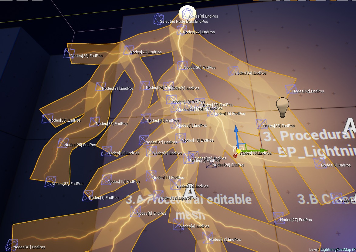
Mesh editor
Lightning Fast package contains mesh editor BP_LightningMesh that allows the creation of unique lighting meshes. Drag and drop blueprint on scene Blueprints/LightningMesh/BP_LightningMesh to start creating a lightning mesh.
Each mesh is generated from a node list (attribute Nodes array). The node list is an array that contains a graph of connections between nodes described using a special structure called BS_LightningNode.
BS_LightningNode
Description
Parent
This attribute describes the index from an array of the parent nodes. Each node has a parent. If the parent of the node has the same index as the source node then the parent is the root(starting point) of the hierarchy generated from the node list.
EndPos
Location of the ending point. It can be edited visually in the main viewport as well by selecting and using translation gizmo.
Loop
A value higher or equal to 0 is the index of the loop endpoint. The -1 is the default and means that there is no loop.
Width
Node width.
Priority
Higher priority means that the node describes the main branch.
TangenInOut
The scale of the tangent input-output vector.
Lightning mesh during editing on the level. Node 0 is the root.
The package comes with additional tools that help to create unique lightning meshes in the Unreal Engine 4 editor. There are two methods of editing the Nodes array.
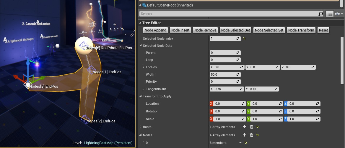
Editing by hand using Tree Editor
Editing using Tree Generator
Tree editor
Tree editor is the basic method of editing the node list multiple buttons increase the speed of building the new branches of lightning mesh.
Editor Buttons
Description
Node Append
Append the child to the selected node (selected node index).
Node Insert
Divide the selected node (selected node index) by inserting a node in the middle.
Node Remove
Removing the selected node (selected node index).
Node Selected Get
Load data from the selected index to Selected node Data.
Node Selected Set
Save data from Selected Node Data to the selected node (selected node index).
Node transform
Transform a selected node by Transform to apply the attribute.
Reset
Clear the tree.
Tree generator
Lightning Fast has an advanced system of mesh generators that can be used to automatize the creation of wide-range meshes.
Working with generators is simple:
Add the generator to the Generator List used by the BP_LightningMesh editor.
Chose the class of generators LTG_Branch
Click Evaluate All Generators
Double-click on the generator instance edit parameters and click “Evaluate All Generators” again.
BP_LightningTreeGenerator is the base lightning generator class that can be extended by other generators by overriding the Evaluate function.
Example generators provided in version 1.0 of the package are described below:
LTG_Branch – Example generation that creates branched lightning effects.
LTG_Spline – Example generator that creates lightning based on spline shape.
Create static mesh
A generated mesh can be easily converted to static mesh and used in other blueprints and particle effects. A few steps are needed to do this:
Select BP_LightningMesh blueprint and find the component called ProceduralMesh
Find option UseDynamicMaterial and set it to false.
Click the button Create Static Mesh
Select where to save the mesh
UseDynamicMaterial = false forces system to use default not instanced material. If you will skip this step then newly created meshes will contain reference to instanced material ant wont save.
Questions & Answers
Integration with Fast Stylized Procedural Sky?
Yes! Last update of Stylized Procedural Procedural Sky supports integration with Stylized Procedural Sky just place lightning bolt on map and activate it on event from build in lightning system.
It is worth buying?
Hell yes! After four mounts of:
researching the topic,
watching thousands of photos and videos with lightning effects,
testing multiple solutions,
removing huge amounts of unsatisfying effects
hard time spend on iterations and optimizations
I can ensure you now that it's not worth to do it by yourself from the beginning when you have finished solution and my support. I would never start again if I would could... 😉
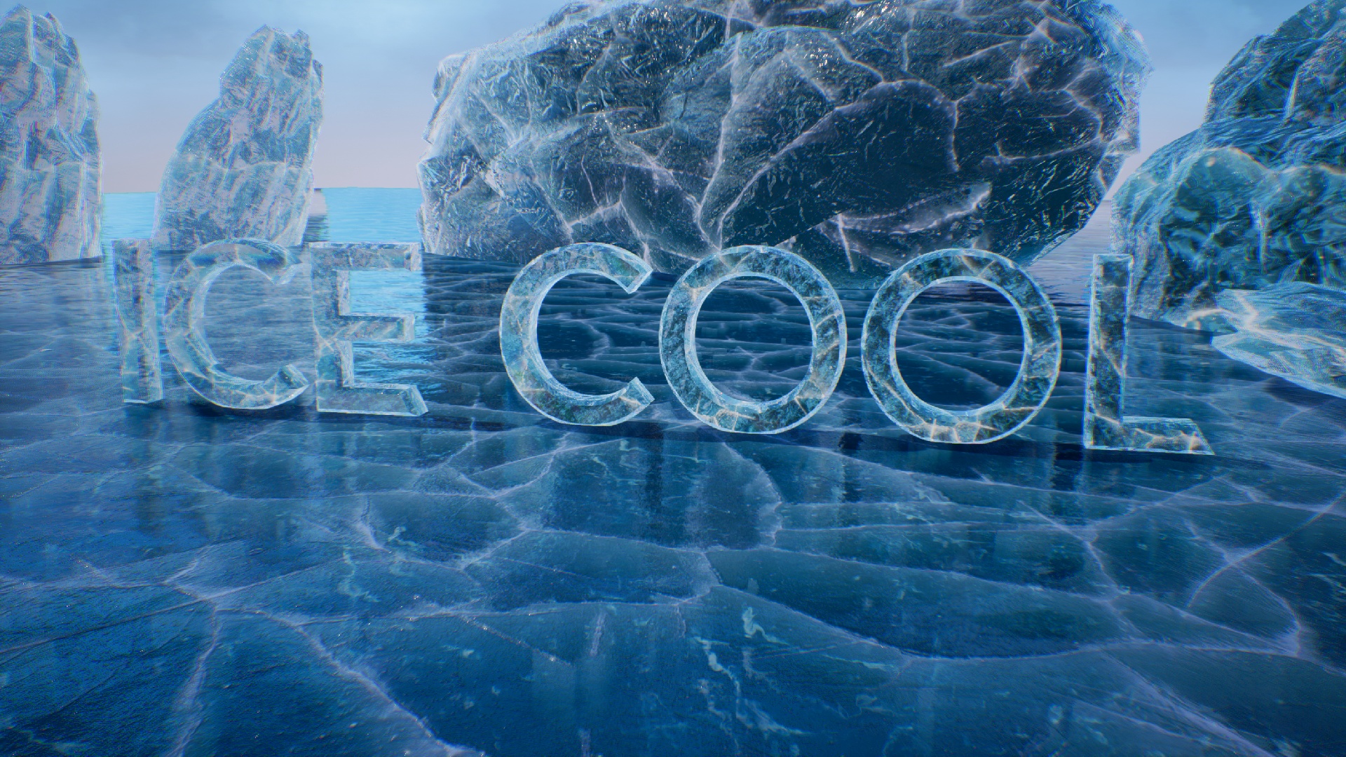
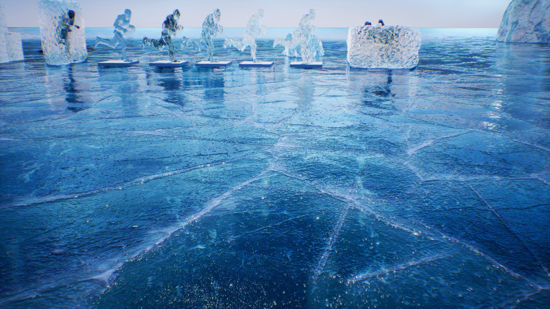
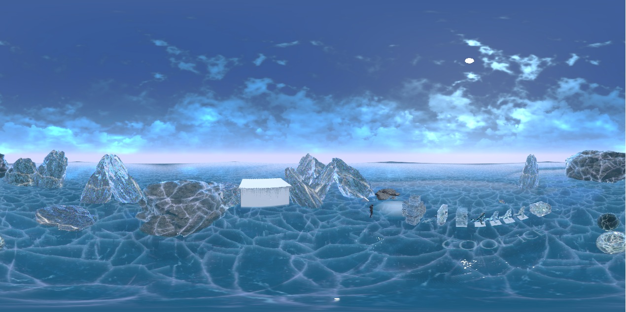
I am pleased to inform that the package Ice Cool is already available on the marketplace. [Link]
Description
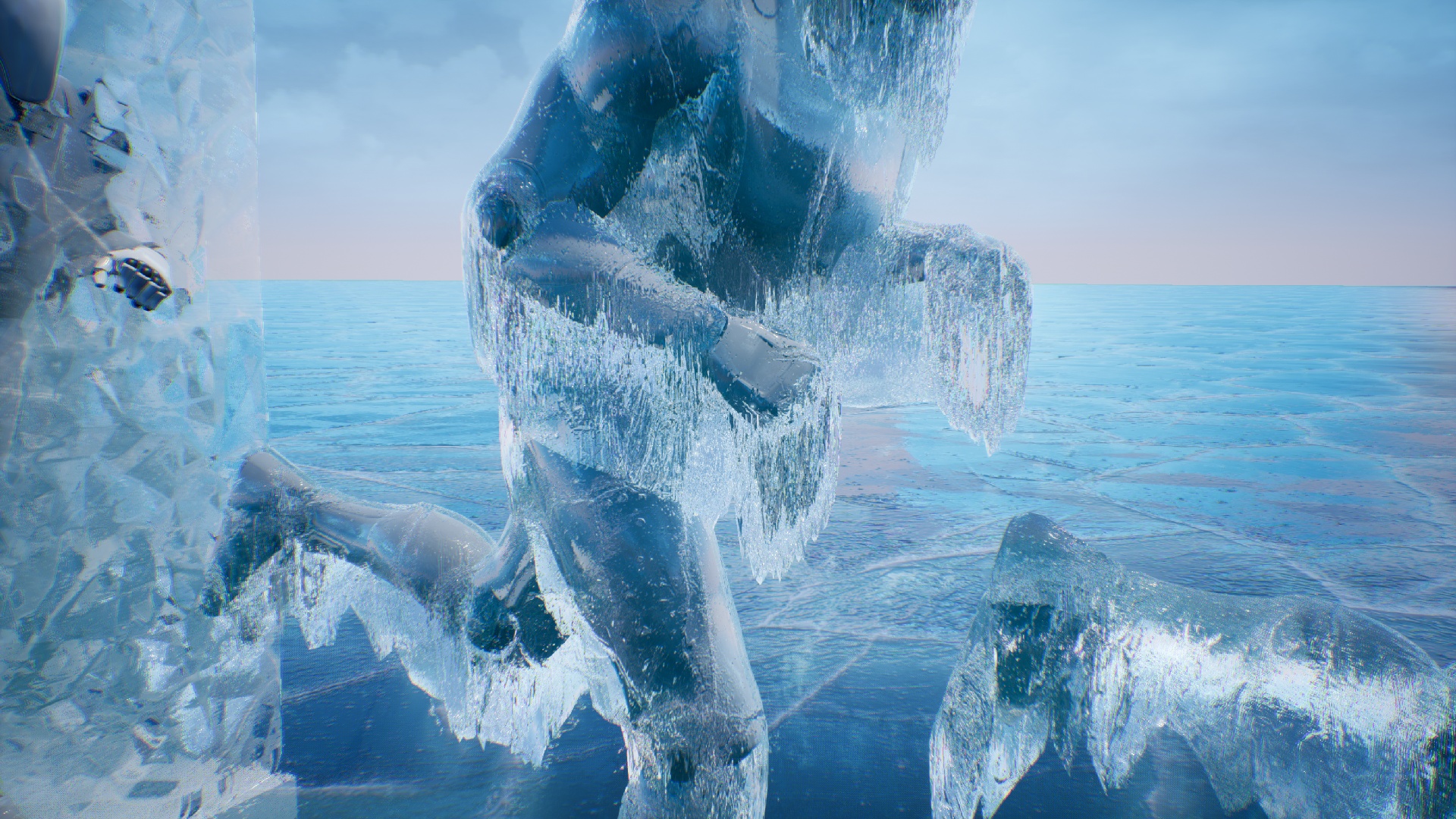
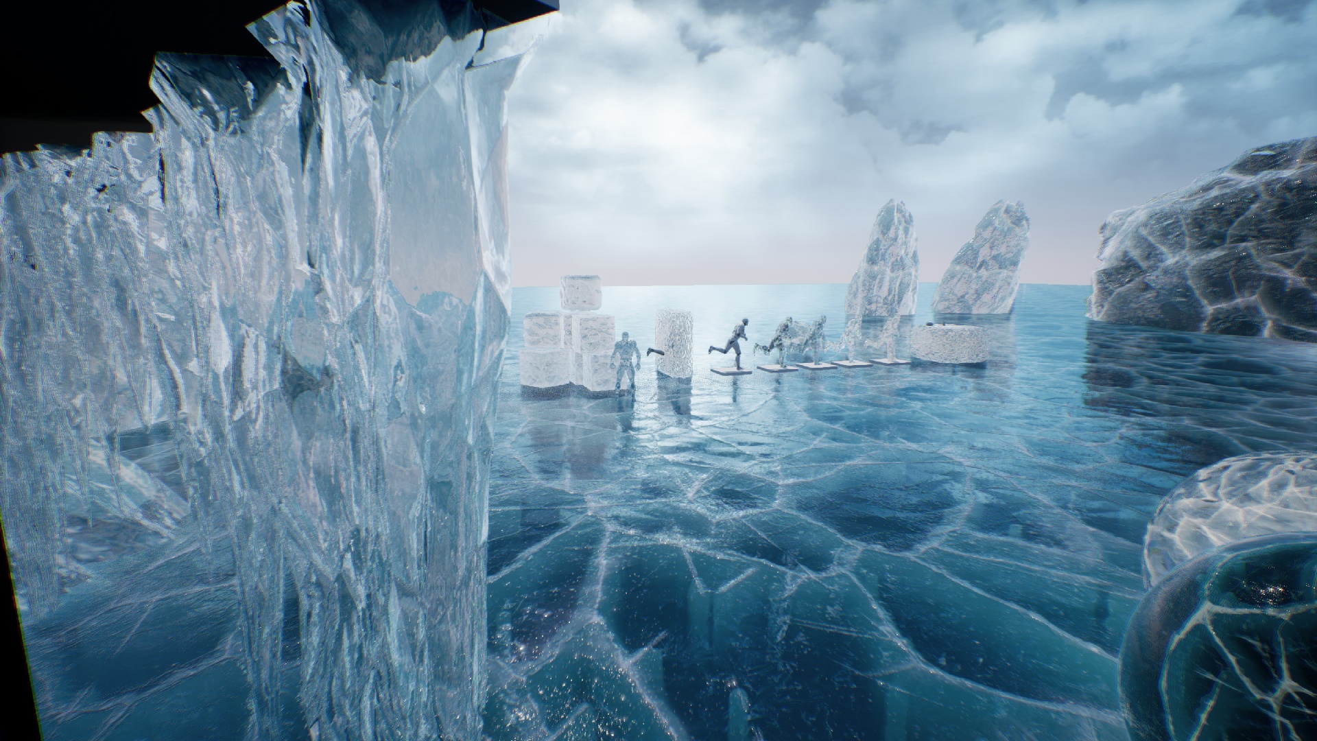
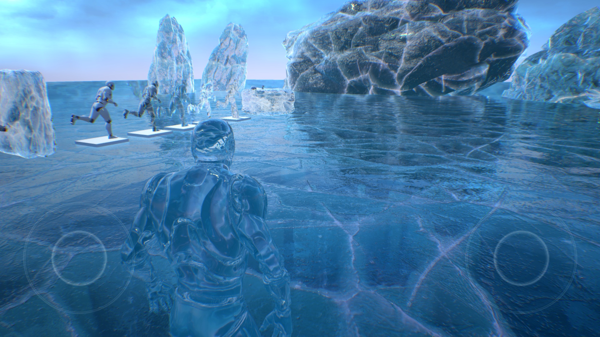
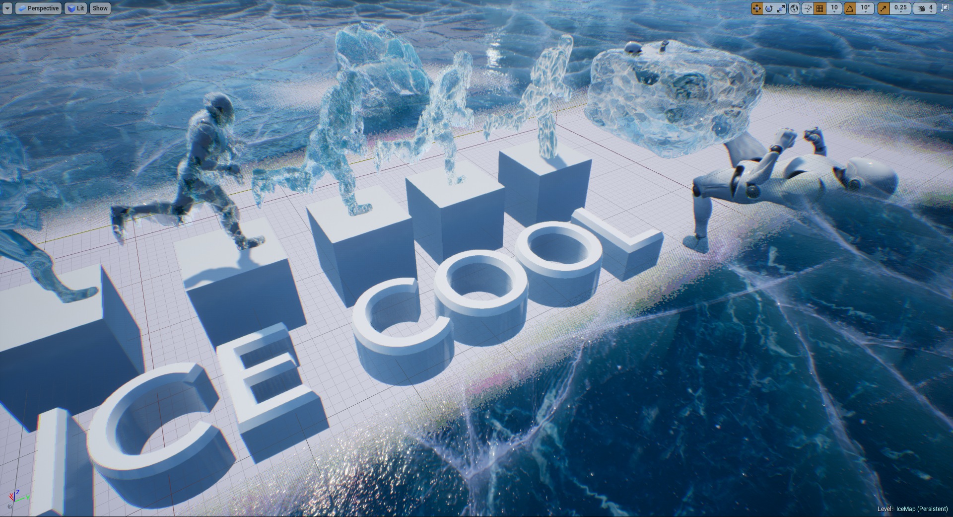
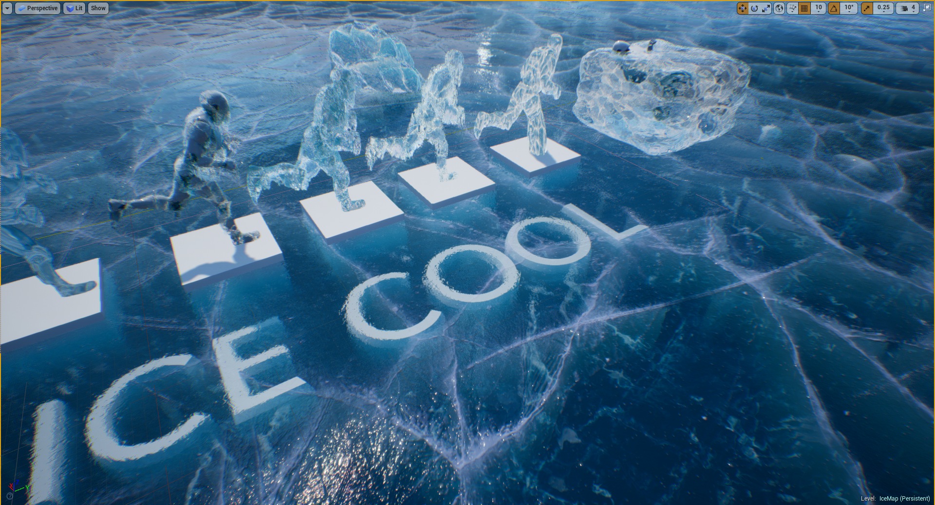
Ice Cool is an advanced master material prepared especially to create multiple types of ice like ground ice, ice cubes, icebergs, crystals, glass, and icicles. The translucent material option is a great solution for improving your level by storytelling on cold Arctic maps. Designed and optimized specially for Mobile, Virtual Reality, and stylized PC/Console games.
Features
Customization options. Over 200 parameters to make it look cool. Additionally, Over 50 switches allow controlling efficiency-quality trade-offs.
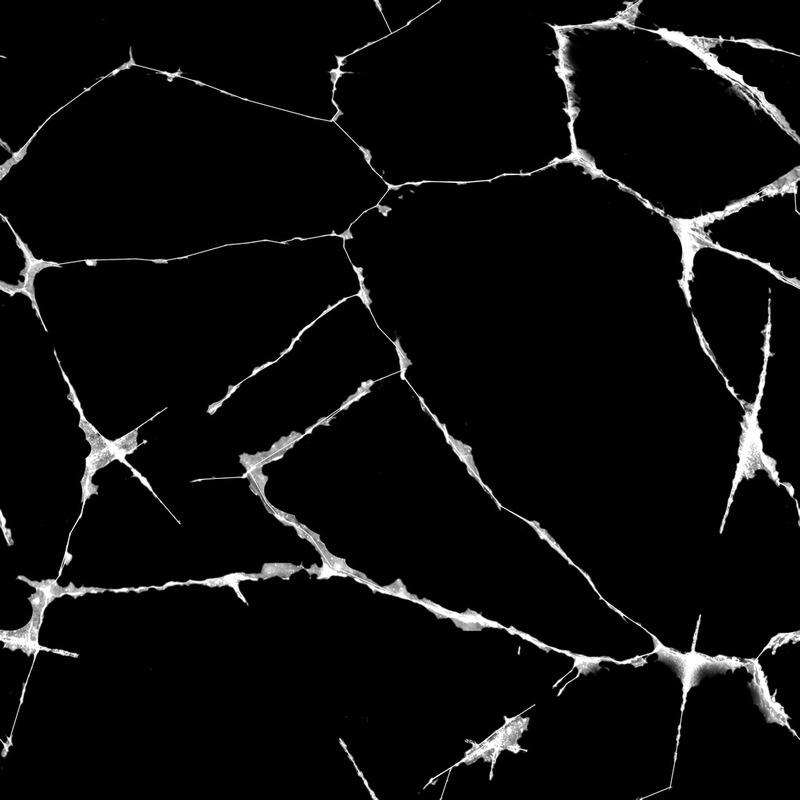
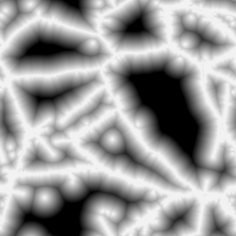
Uses the NEW FAST cracks rendering method. Implementation of the new cheap iterative technique of parallax for rendering deep cracks based on Signed Distance Field Textures. Thanks to using the SDF result effect stays clean and smooth even on closeups with using only 7 texture reads! (5 times faster than other methods).
Supports multiple types of refraction. Supported cube map with box projection mapping/screen color/built-in refraction pin.
Advanced translucency options. Translucency supports depth-fading fog for a better quality of covering the objects inside the ice.
Subsurface scattering and custom lighting. Useful for more advanced users to better fit the ice into the scene.
Extended reflection mode. The system supports pre-rendered cube map reflections mapped on meshes using box projection mapping and spherical mapping. This method is very fast even on translucent materials.
Icy vertex offsets. Material supports configurable Vertex displacement for Icicles.
Masked dithering. You can configure the system to use translucent material only where you need it and dither the opaque material around the wholes.
Animated dust. A configurable dust map with refraction noise makes the material look even deeper and real.
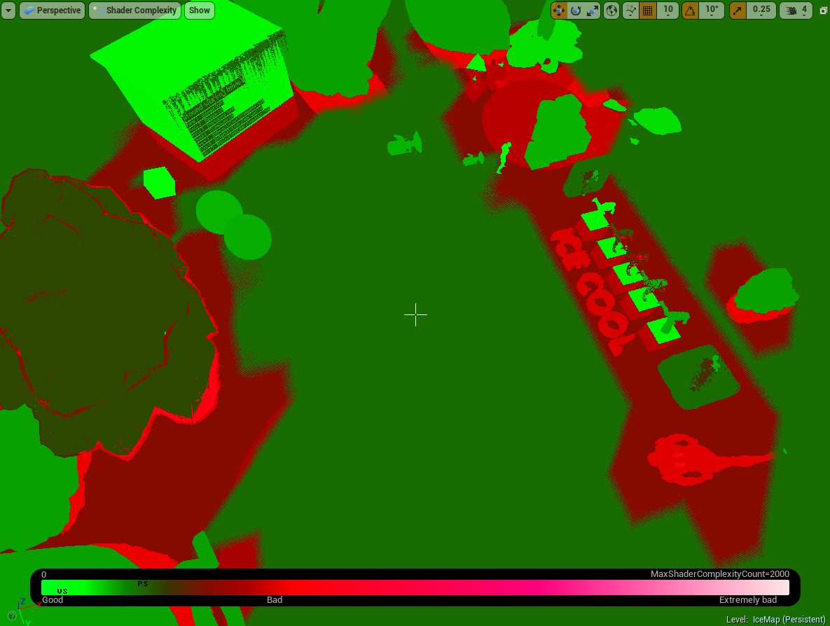
Efficient and GPU friendly. Uses between 90-210 instructions depending on the number of features enabled can be used on VR and even mobile.
Extra tools. The system includes additional tools for generating new Signed Distance Fields and environment cube maps.
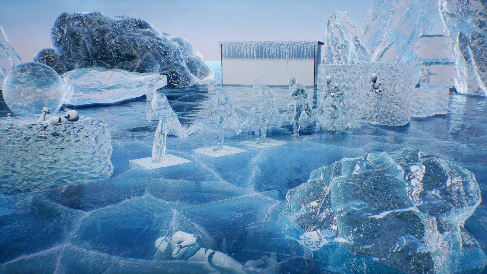
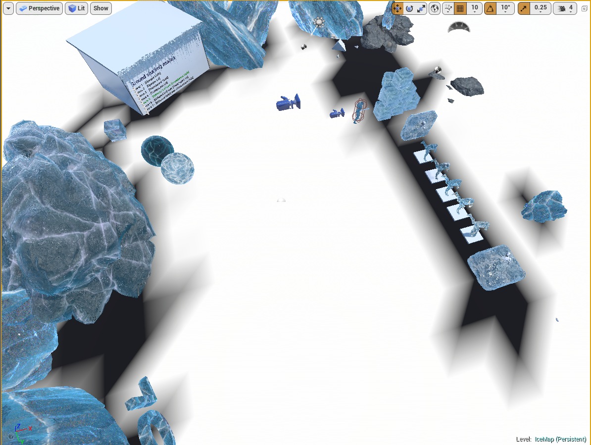
Multiple useful examples. The package contains an example map with a showcase of multiple samples of using the material.
Gallery
Documentation
Get Started
Ice Cool is a pack based on a single advanced master material. The material is placed in the folder IceCool/Materials/M_IceCool. Every user has two ways of working with the package.
Copy Material (Easy one) – Copy example material and modify the parameter to fit the requirements. You can check the example materials in the demo IceMap.
Create Material (Hard one) – Create a material instance from master material and set material parameters from scratch.
This documentation covers both approaches to creating cool ice material.
It is good practice to create New Folder where the materials created using Ice Cool package will be stored. Try to not modify or add any content do the Ice Cool package it will protect your project from problems after downloading the new updates of the package.
Copy existing material
Ice Cool package contains a demo folder with multiple examples of materials of ice prepared for the specific conditions that can be copied to your project. All examples of ice materials are stored in the Demo/ExampleMaterils folder.
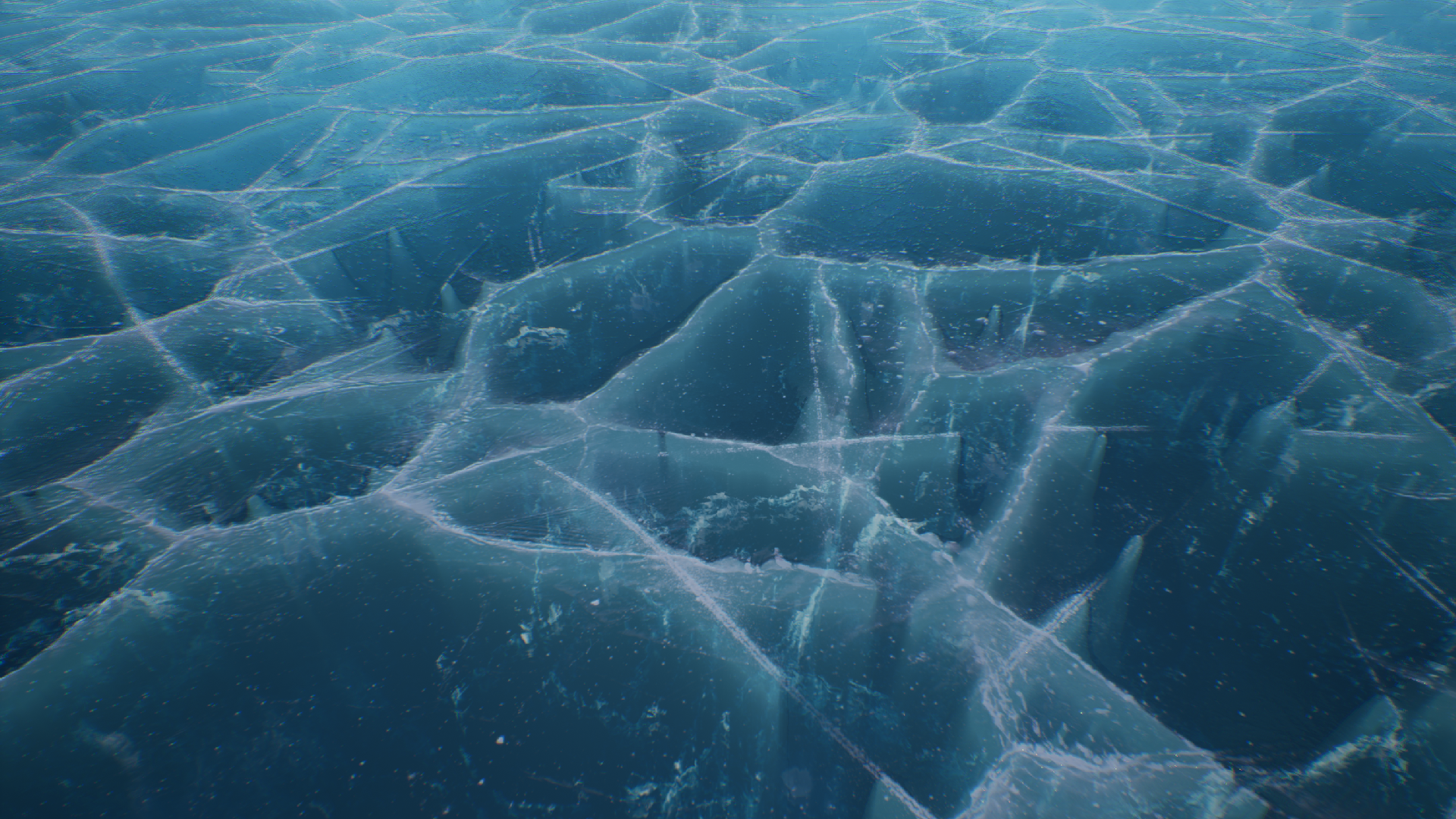
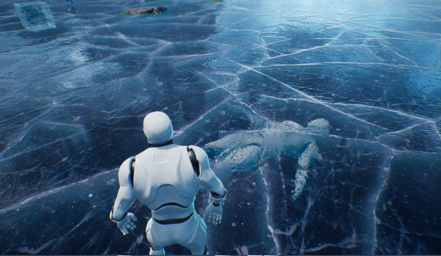
Cracked ground
Half-translucent ice cubes
Opaque icebergs
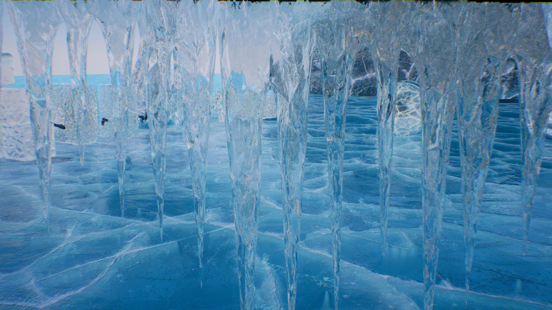
Translucent icicles
Ice coating
Select material that you want to use in your game
Click the right button on the material and choose duplicate (if you want to copy) or create a material instance (if you want to extend the material and modify parameters).
Move the newly created material into your project folder.
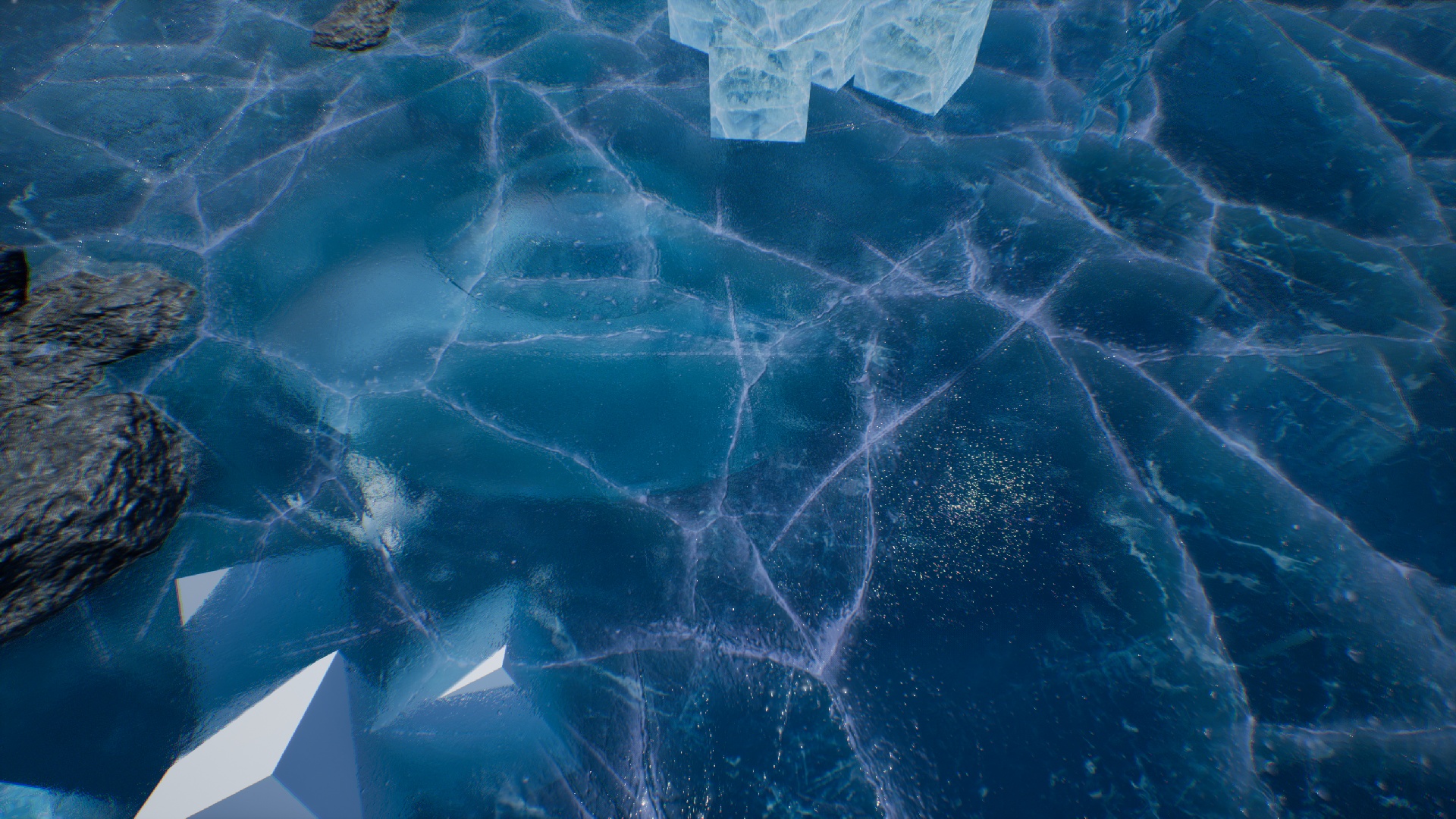
Cracked ground
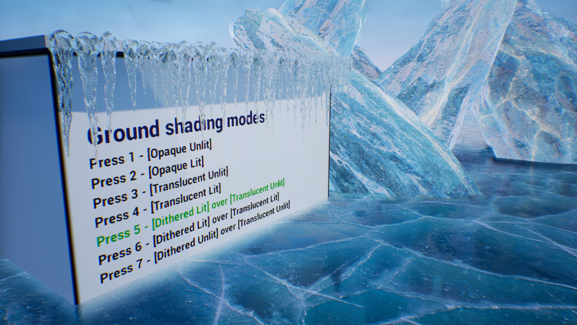
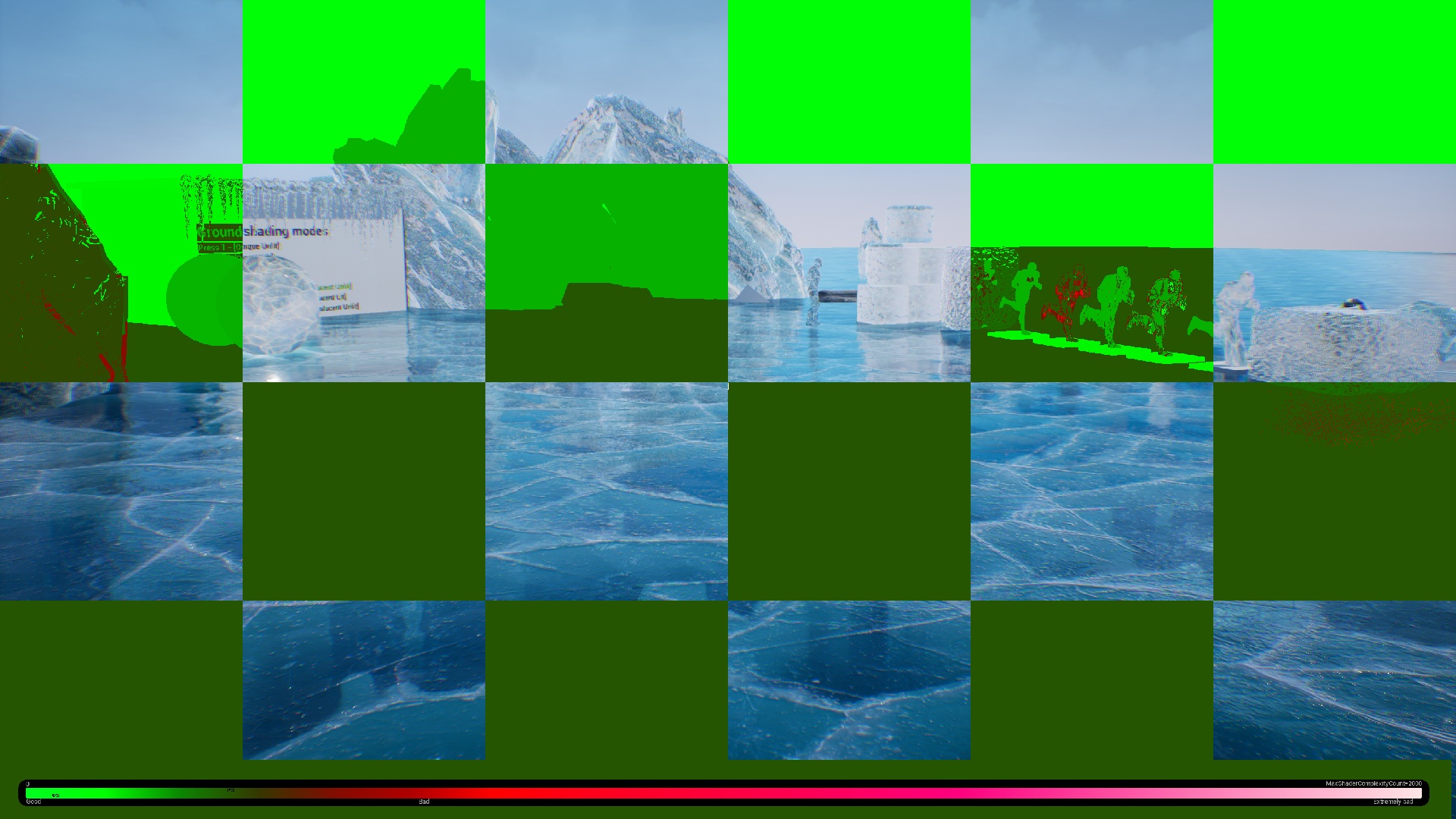
The cracked ground is the most advanced use of the Ice Cool package. This material is prepared to be used as a ground. The UV coordinates of ice texture are calculated in the world space so the material can be used regardless of mapping or ground size. There are multiple types of this material prepared to fulfill the requirements of quality and platform type that the game targets. The demo allows seeing differences between every type of material by pressing keys 1-7 on the example map.
Material Type
Lighting
Reflections
Platform
Opaque Unlit
Material parameters
Cubemap
All
Opaque Lit
Build-in UE4
Reflection Captures
All
Translucent Unlit
Material parameters
Cubemap
All
Translucent Lit
Build-in UE4
Cubemap
PC
Dithered Lit + Translucent Unlit
Mixed
Cubemap near the camera.
PC
Dithered Lit + Translucent Lit
Build-in UE4. Best quality.
Cubemap near the camera.
PC
Dithered Unlit + Translucent Unlit
Material parameters
Cubemap
PC
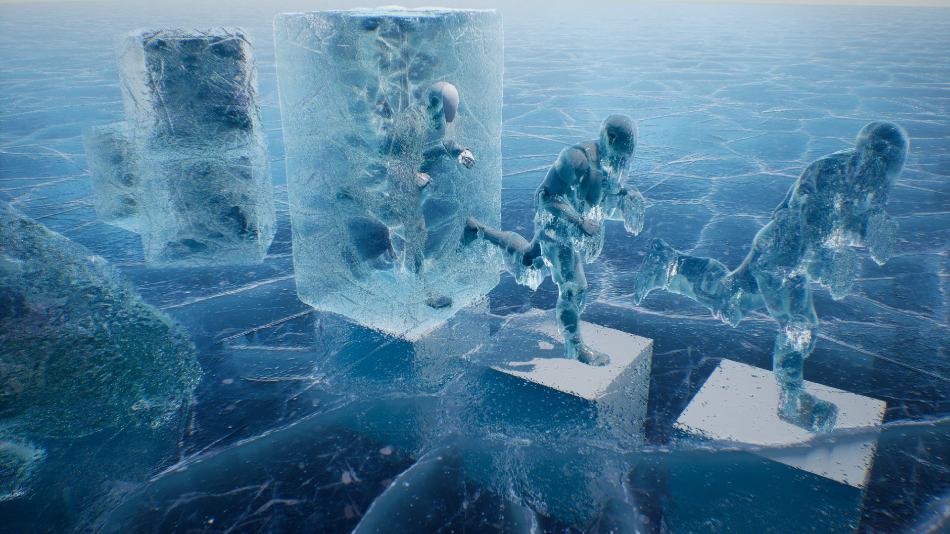
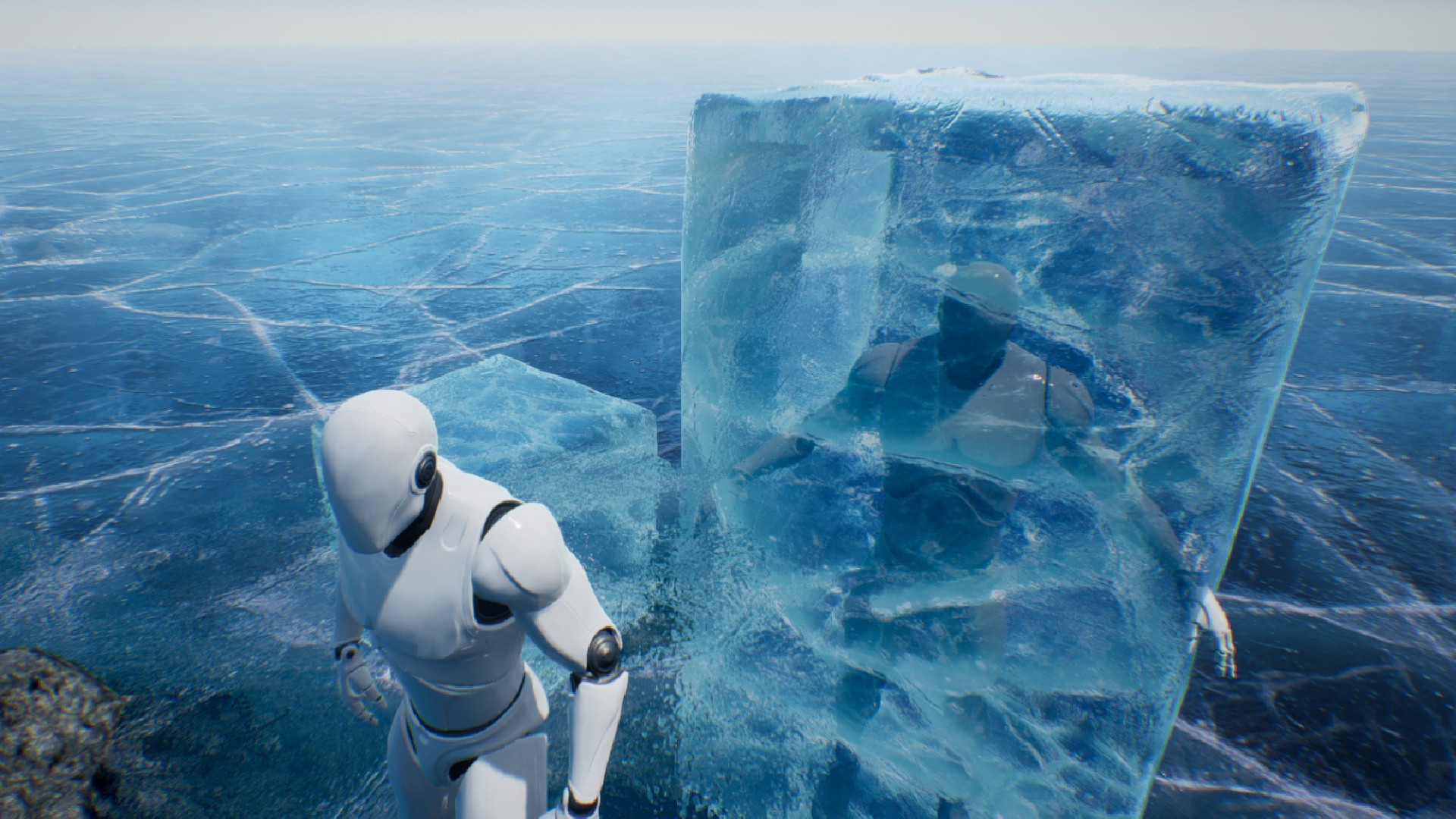
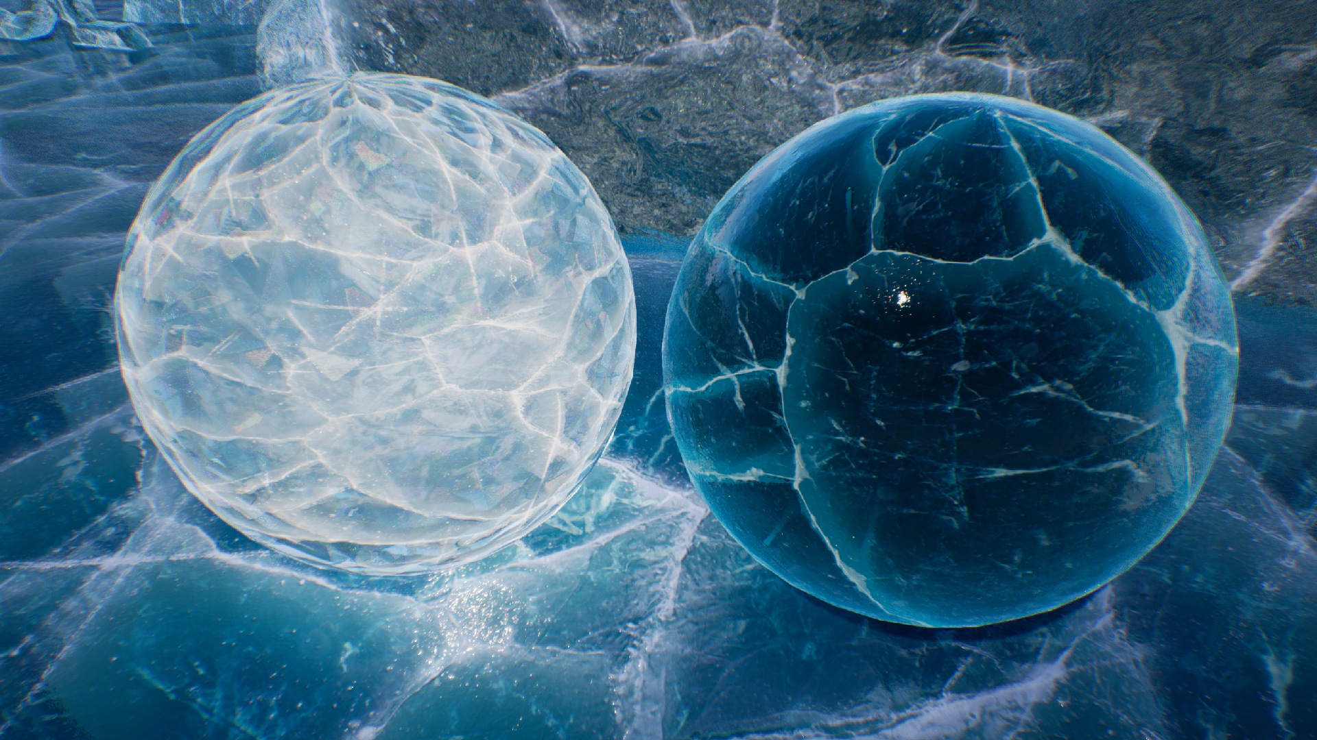
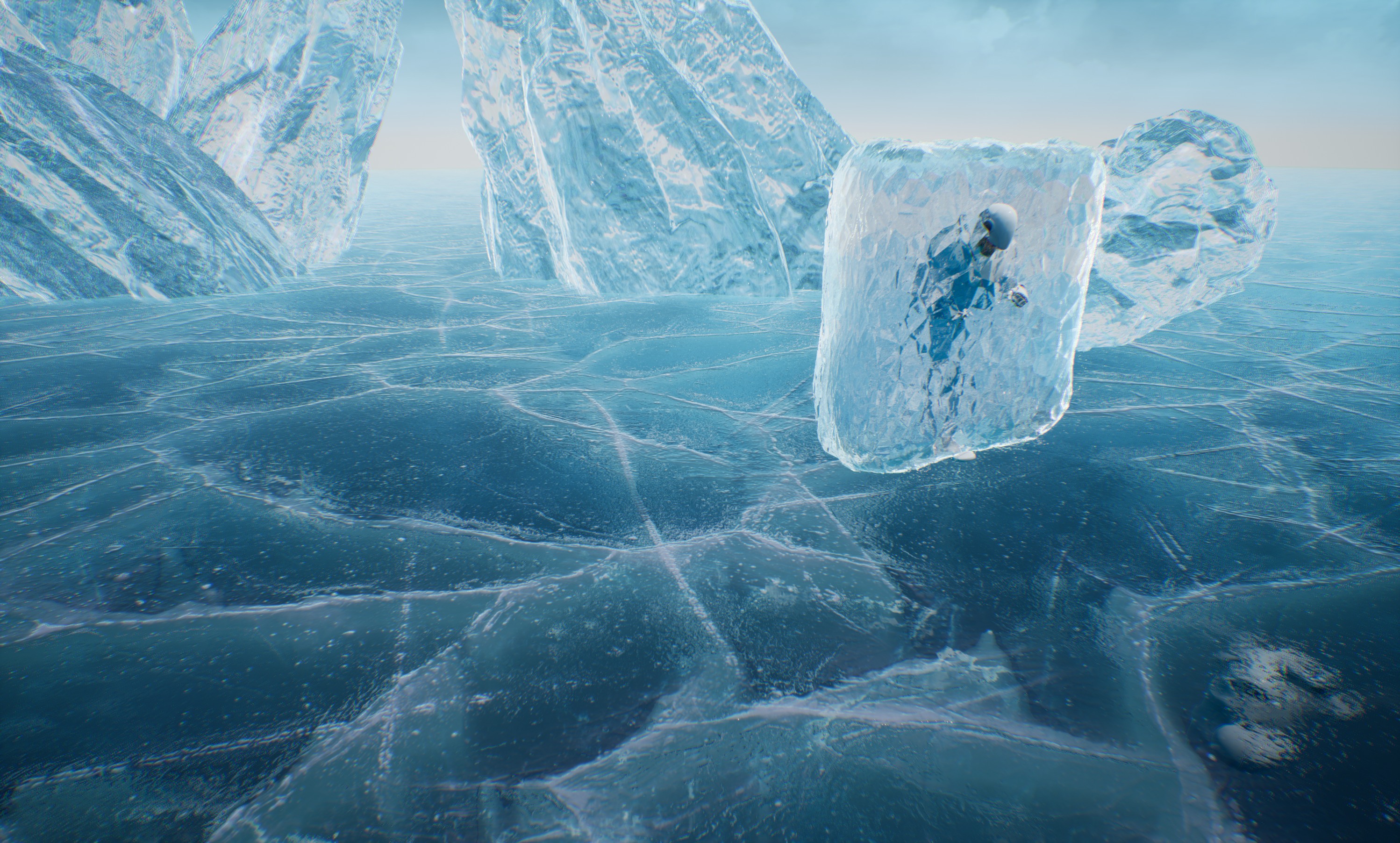
Half translucent cubes
Half translucent means that this type of ice is a combination of two meshes opaque and translucent.
Inside layer (MI_IceBlockBigInside) Opaque mesh is rendered from inside of the geometry (normal inverted front face culling)
Outside layer (MI_IceBlockBigOutside) Translucent mesh is rendered traditionally as a layer over the ice.
This kind of material is useful when you want to put some meshes into an ice cube and achieve good effects of refraction. The mesh will be rendered between the inside and outside layers.
Half translucent ice based on two materials – mannequin mesh placed inside the ice.
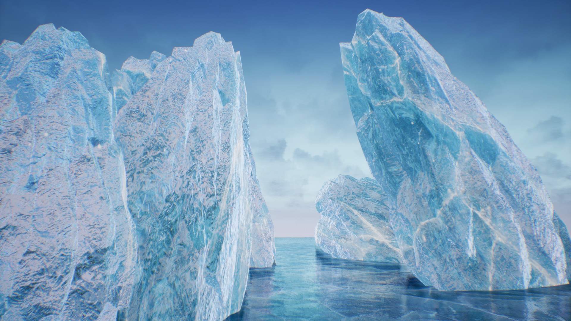
Opaque icebergs
Very efficient good-looking looking opaque material useful for icebergs that use refraction based on external cubemap.
Opaque iceberg material in action
Translucent icicles
This material type was prepared especially for creating icicles hanging from a roof. The additional layer of animated dirt makes it look wet.
Translucent icicle material in action
Create new material
If you are not interested in using predefined materials of ice then there is always the harder path to follow. You can remove all demo content and create the material instance from scratch.
Find the base material IceCool/Materials
Duplicate the MI_IceCool or create a material instance from M_IceCool.
Rename newly created material and move it to the Ice Materials folder in your project.
Material is ready to use from now on.
I’m not recommending you this method. It requires a lot of knowledge about the ice material and this documentation does not cover all details yet.
Reflection
The reflection effect is based on pre-rendered cube maps. A detailed explanation of how to create a cube map for ice can be found in the Tools/Cubemap Rendering chapter. Ice materials support two types of reflection mapping. Spherical reflections and box projection mapping.
Spherical mapping – Very fast but inaccurate. Works out of the box.
Box projection mapping – Very accurate in box-shaped rooms. Requires additional room-size pieces of information in the materials.
Box projection mapping
UseBoxProjection
Allows using box projection mapping. If disabled then the system uses standard spherical cube-map projection.
ReflectionBoxExtend
half the size of the room cached in the reflection map.
ReflectionBoxPosition
Position the camera where the reflection was cached.
UseReflectionBoxLocal
Forces system to use reflection box capture in local space of actor position. Useful when the mesh is connected to the same actor as the reflection capture component.
Other reflection parameters:
Reflections
ReflectionColor
The color of the reflection allows for adjusting the cube map to underwater conditions. An alpha channel represents the power of Fresnel.
ReflectionTexture
Prebaked cube map reflection texture should be cached in a place where the glass is rendered.
Use Shlick Reflection
Enables physical-based Shlicks Fresnel calculations. Otherwise use fast simplified dot(camera, normal) Fresnel.
UseReflectionBoxLocal
When true then ReflectionBoxPosition will be added to the actor position.
Refraction
The package supports multiple advanced types of refraction. Each type of refraction is useful for a different scenario.
Build-in UE4 refraction
Screen color refraction
Opaque cube map refraction
Fast dithered layers
The dithered material is the composition of two meshes with the top layer implemented as dither translucent. That combination allows using the slow translucent materials only where it is needed and increases the quality of lighting and reflections at low cost by using the opaque material over the translucent.
The top mesh layer uses opaque dithered material that has high-quality reflections and lighting implemented by Epic.
The bottom mesh layer uses a layer of translucent material that is covered by the top layer using a dithered transition.
It’s good practice to use bottom translucent layer only where it is needed and cut invisible parts of this mesh to increase a performance by lowering the geometry overdraw.
Dithered material can be masked by a vertex color alpha channel painted in the vertex paint mode. This functionality is active only when the UseDitheringVertexAlpha option in the top opaque material is active.
Material parameter
Use Dithering Distance
Use dithering in distance from the camera.
Use Dithering Vertex Alpha
Use masking of the dithering by vertex alpha.
Use Dithering Per Vertex
Calculate the distance for dithering per vertex to lower the shader complexity. It can cause some quality problems when using low-density meshes.
Dithering Border
Dithering distance border.
Dithering Smooth
Dithering border smoothing.
Parallax cracks
Advanced algorithm for rendering parallax cracks uses the information about the distance from the crack to render a very efficient and smooth effect in only 6-8 texture reads. In comparison to other algorithms, it is over 6 times faster and looks much better on closeups.
Material parameter
Use Cracks
Whether the effect of cracks should be used in the material. The cost of this effect is noticeable (about 30-40) instruction so it’s good to enable this flag only when intended to use effect.
Cracks SDF Texture
A signed Distance Field texture was used to generate the effect. A detailed description of preparing SDF textures can be found in the chapter “Signed Distance Fields Rendering”.
Cracks Color
A bottom color of the effect of the cracks.
Cracks Color Light
A top color of the effect of the cracks.
Cracks Depth Iteration
The number of iterations used to calculate the effect. Best results can be achieved in between 5-10 iterations. It’s worth minimizing this value for optimization.
Cracks Depth Step Size
Step size per iteration
Cracks Depth Scattering
Depth scattering scale.
Cracks Depth Scale
Depth intensity scale.
Cracks Depth Smooth
Smoothing of the effect. It should be lowered when there are a lot of holes in the cracks.
Cracks Distortion
Distortion of cracks based on normal.
Cracks Width
Width of the effect. It should be between 0.93 and 1.0.
Cracks Height
Height of the effect.
Parallax cracks in action
Dust
Ice Cool package supports a deep layer of animated dust.
Dust parameters
Use Dust
Whether the dust should be used in the material.
Dust Color
The color multiplier for the dust texture
Dust depth shift
An offset of the dust layer
Use Dust Layered
Whether to use the second layer of dust.
Dust Layer Between
Interpolation of layer rendered in between base layer and mesh surface.
Dust Texture
The texture is used as a dust layer.
Dust Texture UV Scale
UV coordinates (X, Y) and scale(Z, W)
Dust Texture UV Anim
UV animation speed per second (X, Y)
Use Dust World Space UV
Whether to calculate dust UV in world space or take it from UV0.
Use Dust Noise
Whether to distort the dust layer by noise texture.
Use Dust Noise Alpha
Whether to read distortion of UV dust layer from noise alpha.
Dust Noise Texture
Dust noise texture source.
Dust Noise Scale
Dust noise texture UV scale.
Use Dust Noise World Space UV
Whether to calculate dust noise UV in world space or take it from UV0.
Coating
The coating effect extrudes the mesh in a direction created from normal and gravity vectors. The coating effect is useful for covering geometry with ice with additional icicles hanging from a mesh.
Coating parameters
Use Coating
Whether the coating effect should be enabled
Coating Offset
Channels RGB represents the direction of gravity length of this vector represents force. Channel A is a coating size in the direction of normal.
Coating Normal Distortion
Changes noisy distortion in a normal direction.
UseCoatingNoise
Whether to use noise function to calculate random offsets.
UseCoatingNoiseSkin
When true noise will be calculated using Skin vertex position, false force system to use texture UV.
CoatingNoiseScale
Noise irregularity
UseCoatingTexture
Changes noisy distortion in a normal direction.
CoatingTextureUVScale
Coating texture UV modyfikator.
CoatingTexture
The texture is used for the coating effect.
Coating material in action.
Animated coating
Since update 1.1 Ice Cool supports an animated coating effect that can be useful during freezing meshes.
Multiple types of coating growing animation:
SPHERE – UseCoatingSphereAnimation = true. Coating is growing inside the sphere described by (CoatingSphere.rgb – location, CoatingSphere.a – radius)
PLANE – UseCoatingPlaneAnimatio = true. Coating is growing inside the sphere described by (CoatingPlane.rgb – normal, CoatingPlane.a – plane offset)
FLAT – time based evenly growing. Growing controlled by CoatingFlatBlend float (0 – no coating, 1- full coating )
Coating Animation
UseCoatingAnimation
Whether the coating animation effect should be used.
CoatingAnimationTime
Flat coating animation effect blends between no coating and full coating. Should be modified externally by blueprints.
CoatingAnimTranslucent
Speed of showing the coating effect in the translucency channel.
CoatingAnimType
Displacement mode type. 0 – first type, 1 – second type (just check the difference in showing icicles and shell)
CoatingShapeDistanceBlend
The soft blend between no coating effect and full coating is used in a plane and sphere mode.
UseCoatingPlaneAnimation
The coating is growing inside the sphere described by the Coating Plane
CoatingPlane
CoatingPlane.rgb – normal, CoatingPlane.a – plane offset. Should be modified externally by blueprints.
UseCoatingSphereAnimation
The coating is growing inside the sphere described by the Coating Sphere
CoatingSphere
CoatingSphere.rgb – location, CoatingSphere.a – radius radius. Should be modified externally by blueprints.
UseCoatingShapeLocalPosition
Use the local space position of the vertex during sphere/plane calculations.
UseCoatingDebugAnimation
Show example debug animations. Disable when you want to animate manually in the blueprint by using material parameters.
Tools
Ice Cool package contains additional tools that can help to use the full potential of the material system.
Cubemap reflections rendering
Materials use cube maps for simulating the reflection and refraction of opaque materials. Those cube maps can be created using the BP_CaptureCubeMap blueprint.
Place Blueprints/BP_SceneCaptureCube on your map and set up a proper position to capture the scene (the center of the room would be great).
Open the IceCool/Tools folder and select the render target (RT_SceneCapture).
Click right on the RT_SceneCapture and select “create static texture” The newly created texture is ready to use.
Set the reflection texture cube map to the material parameter called ReflectionTexture.
Signed Distance Fields rendering
A signed Distance Field is an image where each pixel contains the distance to the nearest point on the boundary. An additional sign of distance allows determining if the pixel is inside or outside rendered shape. SDF image that looks like a gradient can be loaded from a file or generated by mathematical functions called Signed Distance Functions.
Short description of how to create the SDF texture:
Place the BP_SignedDistanceFiled on the map.
Setup parameters.
Source Texture
The texture that will be used for generating the SDF.
Search Width
The width of the search is the distance in pixels. W*W is the number of iterations per pixel. Big numbers can crash the program.
Texture Size
Resolution of the texture.
Click Generate to update the render target.
Click right on the RT_SceneCapture and select “create static texture” The newly created texture is ready to use.
Use the texture as the CracksSDFTexture parameter.
New package is coming very soon 🙂 Just waiting for final review.
Description
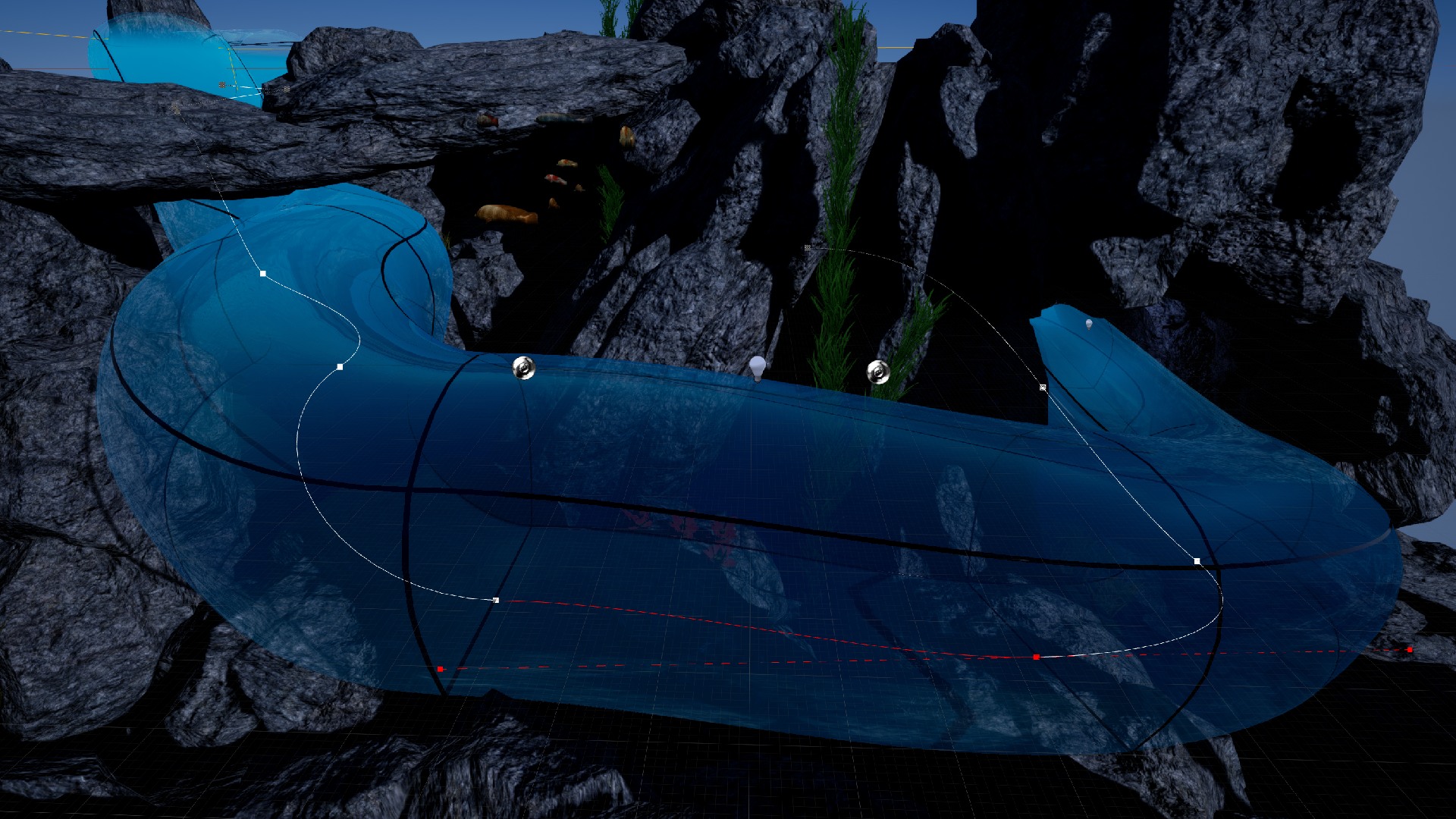
Volumetric Glass is an advanced and efficient master material designed for rendering volumetrics and glass. The package is useful for creating sci-fi stylized environments like water tanks, aquariums, and underwater tunnels even glass in submarines. The package is perfectly balanced between quality and efficiency. Designed and optimized specially for Mobile, Virtual Reality, and stylized PC/Console games.
Features
Two types of material underwater volume and shaped glass
GPU friendly and very efficient can be used on mobile as well as in the VR
GPU friendly very efficient (only 150 instructions)
Over 70 parameters to setup: light shafts, volumetric, scattering, glass color, fog density, wet color, reflections, etc.
Animated clip plane surface
Vertex color based texture masking
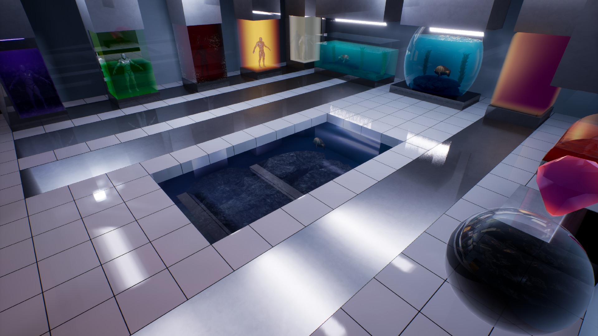
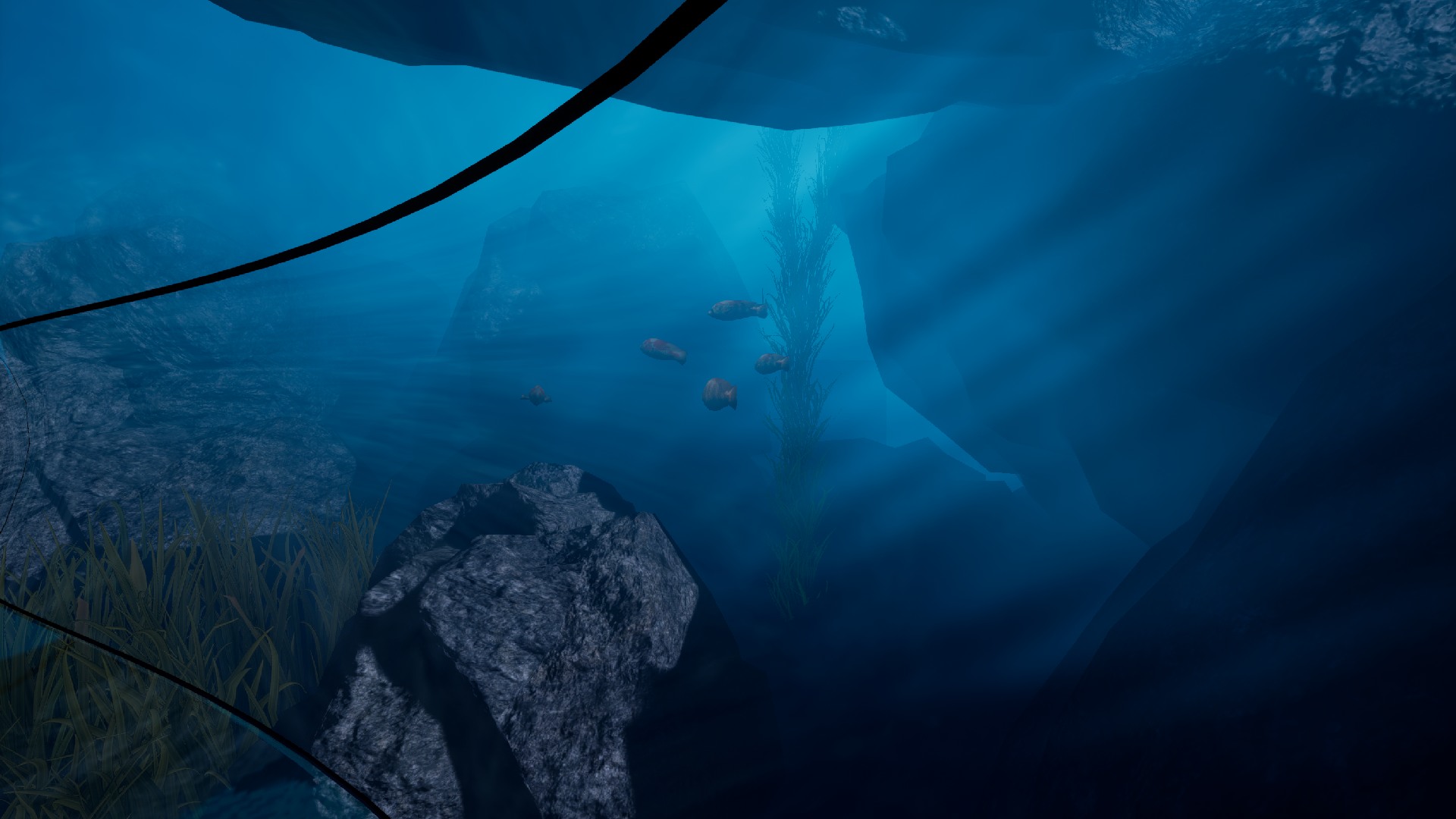
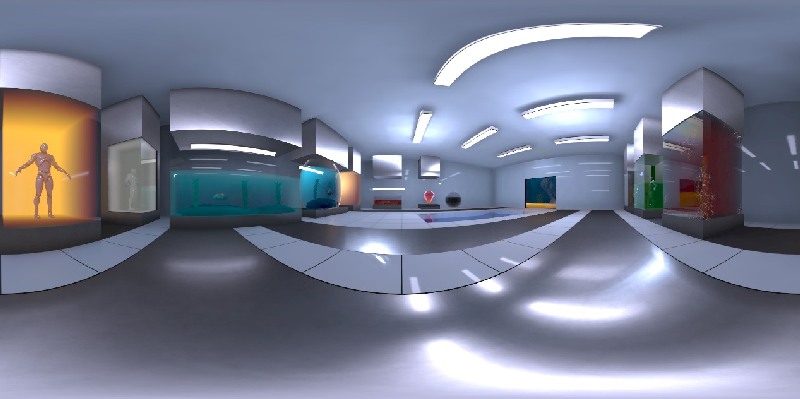
Example map contains underwater world and sci-fi laboratory
High-quality fast scattering
Fast box projected reflections
Custom multi-channeled point lights
Easy for integrating with other water surfaces like Aquatic Surface.
Documentation
Get Started
The most important think about the Volumetric Glass is that the package is divided into two materials specialized for use in different cases:
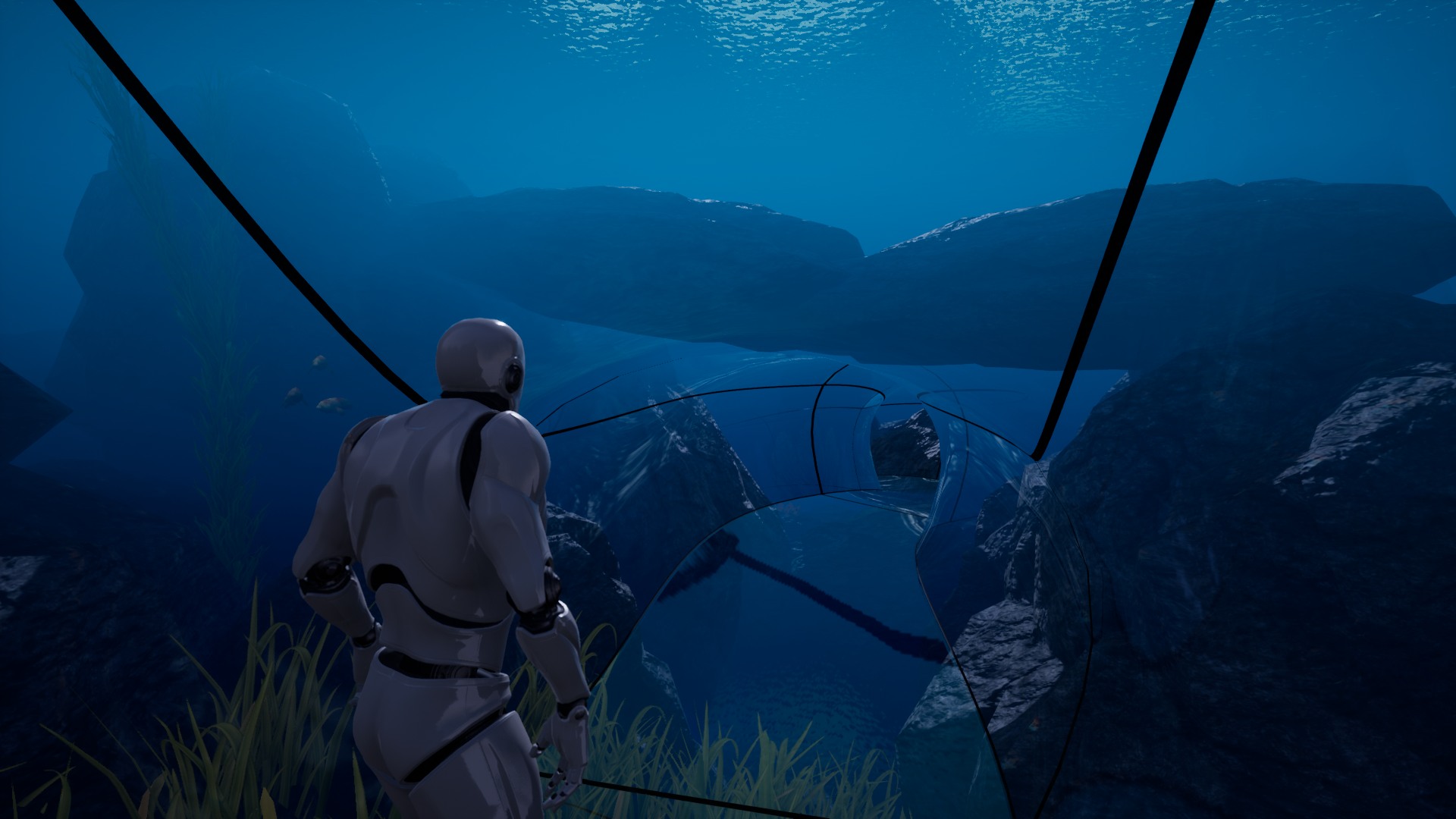
Glass Volume (Materials/M_GlassVolume) – Supports rendering of glasses from the inside of the fluid volume. Represents underwater windows, tunnels, glasses, and world rendered from the inside of the water. Material is called M_GlassVolume.
Glass Shape (Materials/M_GlassShape) – Supports rendering shapes from the outside of the fluid volume. Useful for water tanks sci-fi stylization, volumetric fog used as an environmental effect.
Both materials should be instanced before using on the meshes. To create material instance from the base material click right button on the chosen material and select “Create Material Instance” option.
Glass Shape
Glass Shape material can be used on different geometric objects like a box, cylinder ellipse.
Different shapes of the glass in sci-fi laboratory
Basically, the system requires to use of meshes with unified size (100cm,100cm,100cm) and pivot in the center. The mesh can be scaled properly in actor properties. Example shapes can be found in the Package/Meshes folder.
Example of use:
Chose the shape and place on the map. For example SM_Box
Create a material instance from M_GlassShape
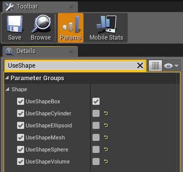
Open newly created material instance and set up the parameters. Find the Shapetab and select the shape that you want to use:
Setup the Reflection Texture cubemap in the material. It should be the texture cached from the scene using the Scene Capture Actor. If you don’t know how to prepare a cubemap read the Capture Reflections chapter.
Apply glass material on your glass on the meshes and see the magic 🙂
It is not possible to use Box/Sphere shaped meshes on the characters props or customization elements because it is not geometric compatible. There is additional UseShapedMesh mode in the M_GlassShape material that implements approximated shape for the undefined shapes.
Base parameters
M_GlassVolume
Use Fog Exp2
Use exponential fog or linear if false.
Fog Base
Base depth of the fog effect.
Fog Density
The density of the fog effect.
Fog Color
Color of the deep fog.
Use Wet Color
Enable wet color functionality.
Wet Color
The color multiplier applied to geometry inside the shape.
Use Translucency
Whether the translucent effect should be active.
Clipping plane surface
Clip plane surface is the effect of clipping the geometry by plane filled by an animated fluid surface.
Clip plane
Use Shape Clip Plane
Whether the clipping plane effect should be active
Shape Clip Plane
Equation of clipping plane RGB-normal, A-translation
Use Surface Normal Map
Use the surface normal map
Surface Normal Map Texture
The texture used as a normal-map.
Surface Normal Map UV
UV scale and translation in an animation of normal maps on two layers.
R – Layer 1 scale,
B – Layer 2 scale,
G – Layer 1 move,
A – Layer 2 move,
Surface Normal Scale
Surface normal z value multiplier before normalization. Allow changing height ow wave.
Surface Normal Flatness
Surface normal flatness. Allow changing height ow wave.
Use Surface Normal Scale
Whether to use Flatness or Scale
Use Surface Normal Map
Use the surface normal map
Use Clip Plane Reflection
Allow using clip plane reflection effect
Use Water Line
Allow rendering waterline on the glass. (experimental)
Lighting
System supports multiple methods of lighting the meshes:
coloring edges of the mesh at lower depth (simple and fast) Use Light Color Edge = true
All of these methods can be used separately or combined at the same time. The only single light source can affect the glass and it can be point light or directional light.
Use Directional Light
True – Use Directional Light
False – Use Point Light
Use Channel = true
Reads the directional lighting values from global settings Materials/UtilsPC_VolumetricGlass DirLightChannel0
Reads the directional lighting values from global settings Materials/UtilsPC_VolumetricGlass PointLightChannel0-2.
Point light channels can be controlled by the BP_ScatteringLight blueprint placed on the level with the selected channels to set.
Use Channel = false
Reads the directional lighting values from local variable Light Direction in the material.
Reads the directional lighting values from the local variable Light Position in the material.
Lighting
Diffuse Power
Diffuse lighting color.
Light Color
Color of light inside the volume.
Use Directional Light
Whether to use directional or point light.
Light Direction
If Use Directional Light = true then uses this value as light direction. Length of vector changes fading.
Light Location
If Use Directional Light = false then this is the default location of the light relative to the actor. Alpha channel contains Attenuation.
Use Light Color Edge
Use the light color as the edge of the shape. The shape will be lightened in depth. The scale of depth can be changed in the alpha channel of the Light Color parameter.
Use Channel 0/1/2
Select which channel will be used as a global point light.
Scattering
Scattering
Scattering Ambient
Scattering ambient value
Scattering Depth
Scattering depth scale
Scattering Depth Block
Scattering blocked by mesh depth inside the volume
Scattering Distortion
Light distortion inside the scattering inside the volume
Scattering Power
Exponential power scattering effect inside the volume
Scattering Sale
The scale of scattering effect inside the volume
Use Lighting
Whether the lighting and scattering effect should be active.
Glass Volume
First, you have to place the BP_GlassVolume blueprint on the scene. BP_GlassVolume represents the shape of the fog volume that will be used for volumetric glass.
Volume is visible only throw the glasses that use specialized material called M_GlassVolume.
Create a material instance from M_GlassVolume and set up the parameters.
Apply glass material on your glass meshes and see the magic 🙂
Base parameters
M_GlassVolume
Use Fog Exp2
Use exponential fog or linear if false.
Fog Base
Base depth of the fog effect.
Fog Density
The density of the fog effect.
Fog Color
Color of the deep fog.
Fog Scattering Clamp
Maximum scattering power.
Fog Scattering Scale
Scale config of the scattering color effect.
Fog Scattering Shift
Shift config of the scattering color effect.
Fog Scattering Width
Width config of the scattering color effect.
Light shafts
Glass material supports simplified optimized light shaft effect settings and configuration listed below.
Light shafts
LightShaftColor
Light shaft color in scattering.
LightShaftDistance
The distance of the light shaft effect from the camera.
LightShaftIntensity
The intensity of the light shaft effect.
LightShaftPosition
Camera position scale when moving light shaft.
LightShaftSpeed
Light shaft animation speed.
LightShaftTexture
The texture used as a light shaft.
UseLightShaft
Activates light shaft effect.
Tunnel Spline
BP_TunelSplineActor is an additional blueprint useful for creating underwater tunnels. To start using this actor just place the BP_TunelSplineActor on the scene and setup parameters.
BP_TunelSplineActor
Static Mesh
Looped mesh used for tube
Forward Axis
The forward axis of the mesh.
Translucency Sort Priority
The priority of mesh rendering. Can fix some translucency bugs.
Hold Alt+Drag the point of spline to create duplicate of spline point.
Capture Reflections
The Volumetric Glass system renders reflections based on the cube maps cached from the scene. It is really efficient method but requires some additional effort to cache the reflection.
Place Blueprints/BP_SceneCaptureCube on your map and set up a proper position to capture the scene (center f the room would be great).
Open Material/Textures and find the render target (RT_SceneCapture).
Click right on the RT_SceneCapture and select “create static texture” newly created texture is ready to use in the volumetric glass system.
Example reflection texture from sci-fi laboratory used on all shapes inside the room.
Reflections Settings
The reflection effect is based on a prerendered cubemap. Volumetric glass supports two types of reflection mapping. Spherical reflections and box projection mapping.
Spherical mapping – Very fast but inaccurate. Works out of the box.
Box projection mapping – Very accurate in box-shaped rooms. Requires additional room size pieces of information in the materials.
Box projection mapping
UseBoxProjection
Allows using box projection mapping. If disabled then the system uses standard spherical cube-map projection.
ReflectionBoxExtend
half size of the room cached in the reflection map.
ReflectionBoxPosition
Position camera where the reflection was cached.
UseReflectionBoxLocal
Forces system to use reflection box capture in local space of actor position. Useful when the mesh is connected to the same actor as the reflection capture component.
Other reflection parameters:
Reflections
ReflectionColor
Color of reflection allows adjusting the cubemap to underwater conditions. Alpha channel represents the power of fresnel.
ReflectionTexture
Prebaked cubemap reflection texture should be cached in the place where the glass is rendered.
Use Shlick Reflection
Enables physical-based Shlicks fresnel calculations. Otherwise uses a fast simplified dot(camera, normal) fresnel.
UseReflectionBoxLocal
When true then ReflectionBoxPosition will be added to the actor position.
Glass Settings
Volumetric glass materials support advanced glass surface configuration that allows customizing appearance to specific requirements. Glass surface is rendered before the volume and can cover the objects behind the glass.
M_GlassVolume
Glass Color
Color of glass mesh (with translucency).
UseGlassTexture
Allow using glass texture instead of flat color.
UseGlassTextureColor
Glass texture color multiplier.
GlassTexture
Glass texture used when UseGlassTexture = true
GlassTextureU
Scale glass texture on U axis
GlassTextureV
Scale glass texture on V axis
UseGlassTexturVertexAlpha
Uses vertex color alpha channel as a multiplier for glass texture. Broken glass example.
Immerse yourself into unstable reality. In order to get out you must exploit glitch in a world around you.
You can be sure of one thing, any rules you known no longer exist! Do you have a courage to dip in it?


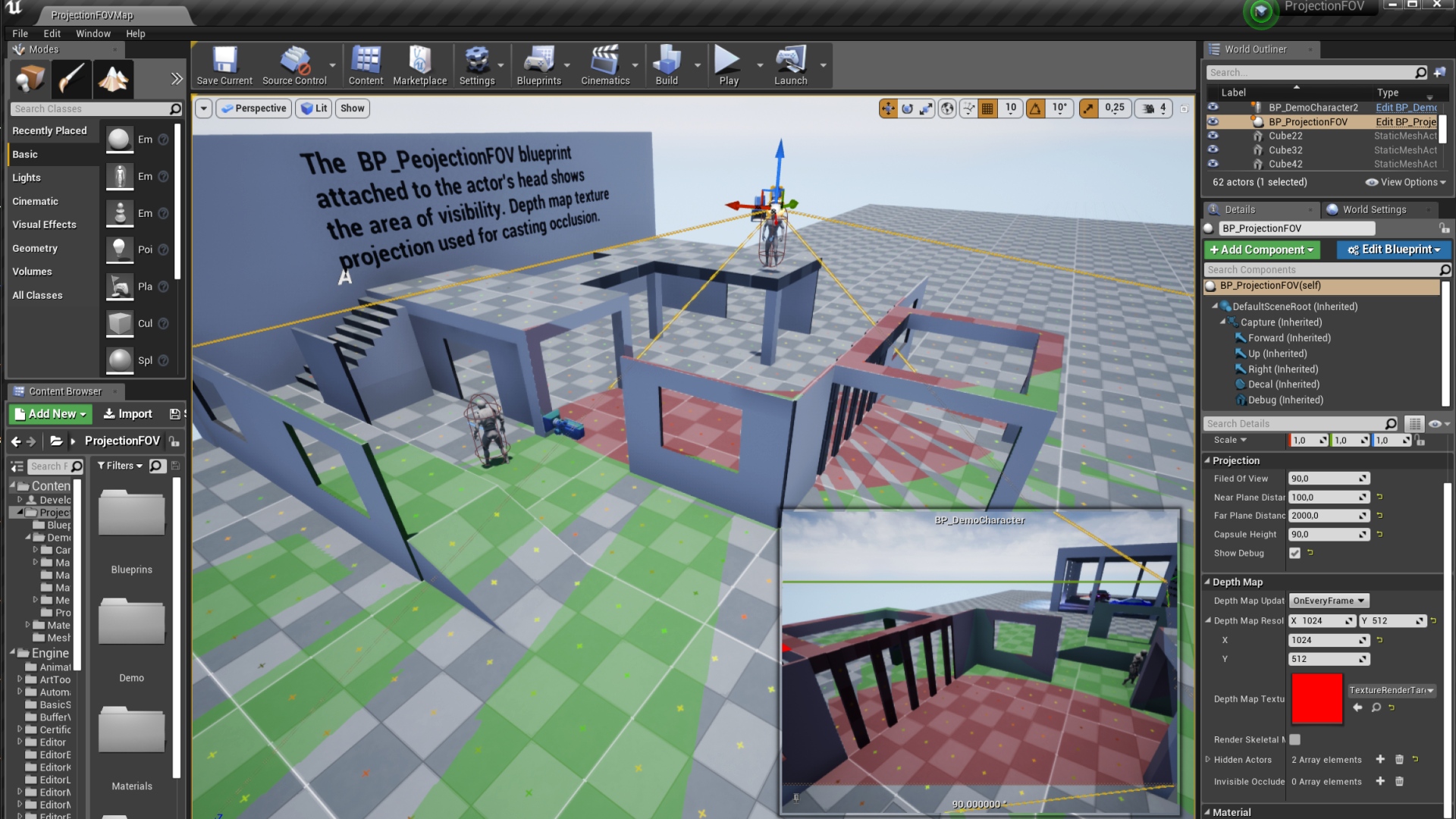
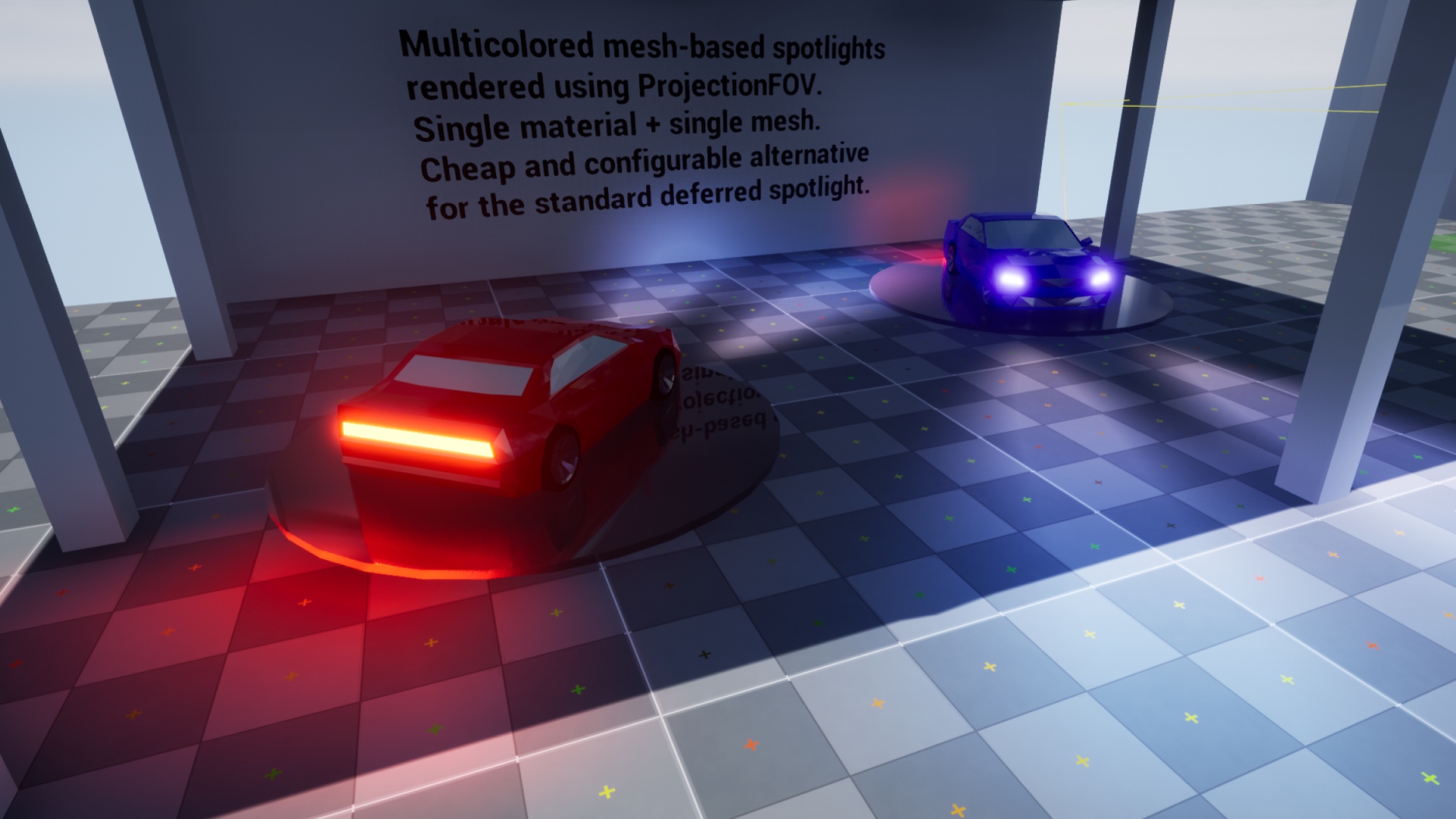
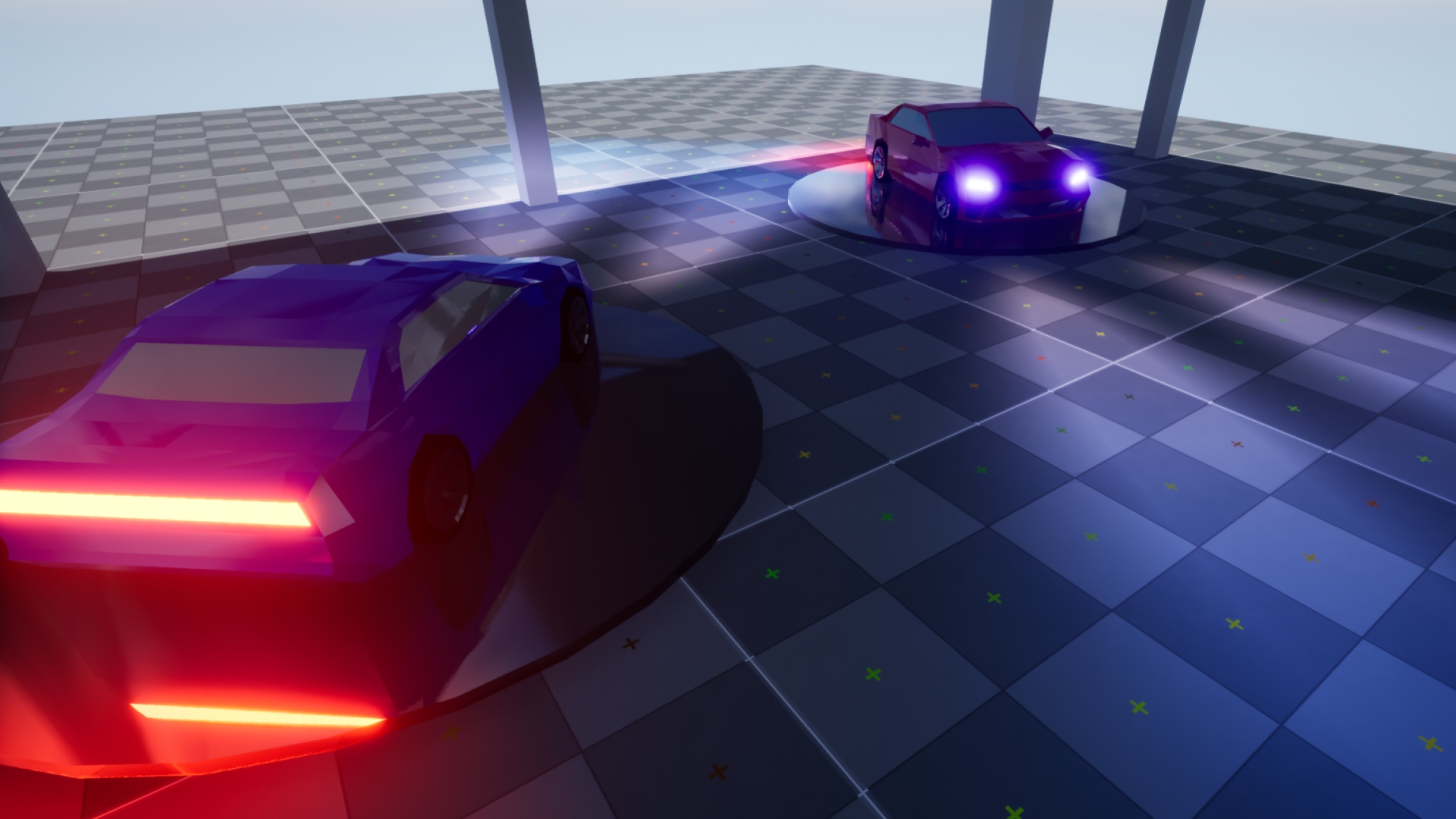
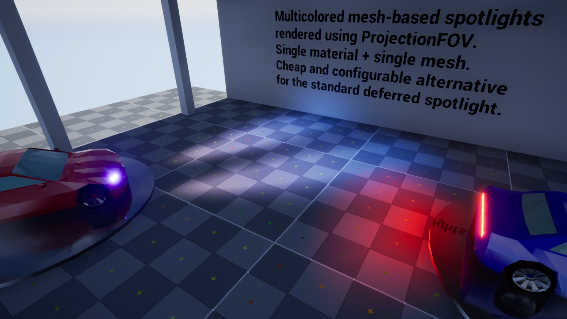
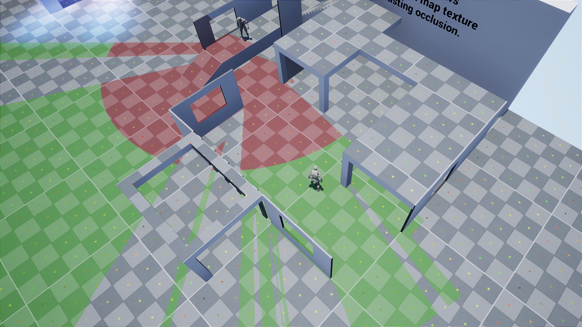
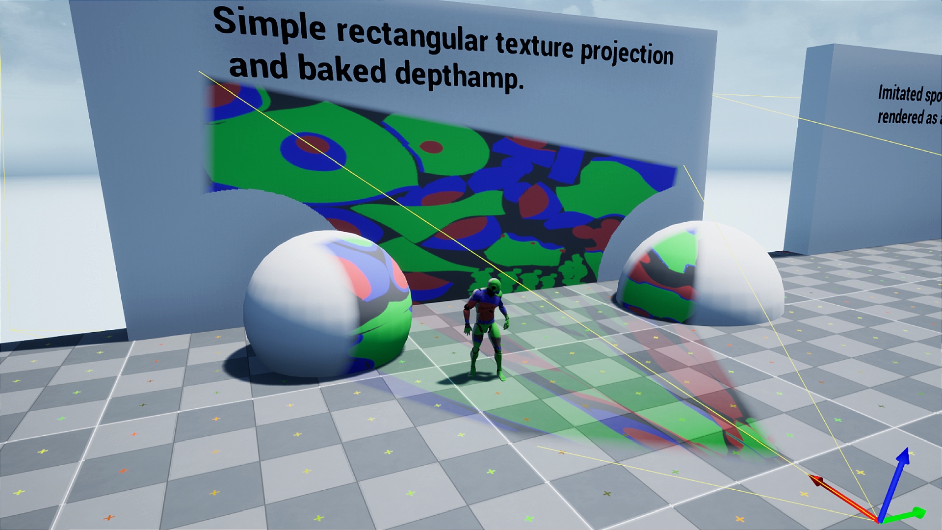
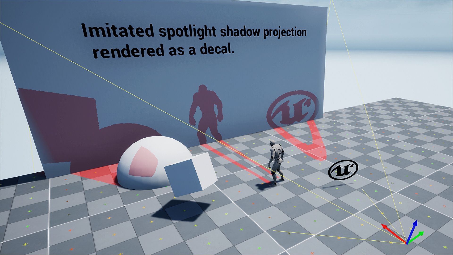
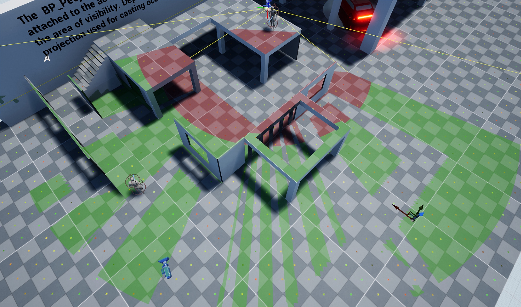
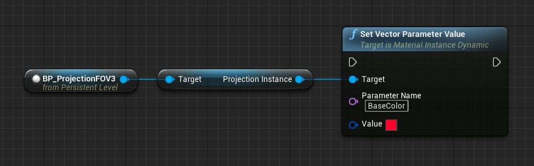


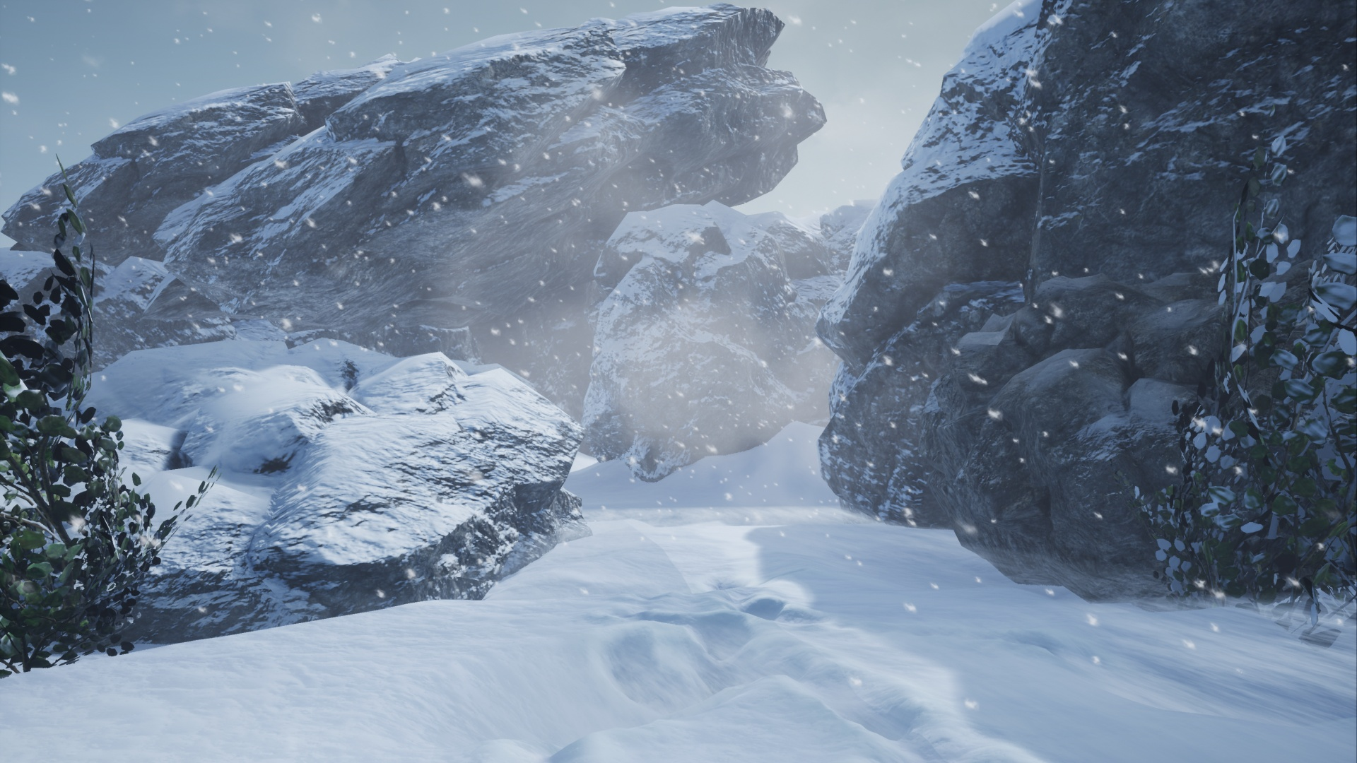
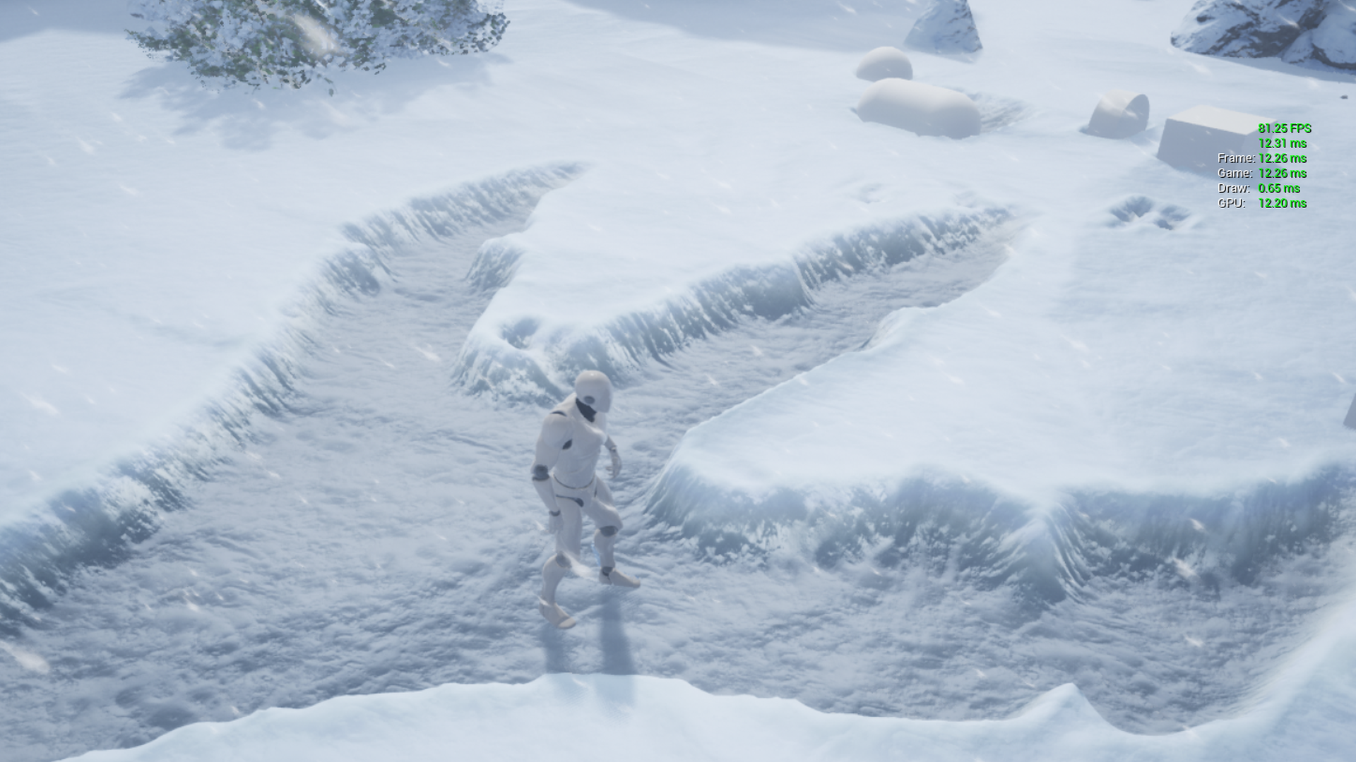
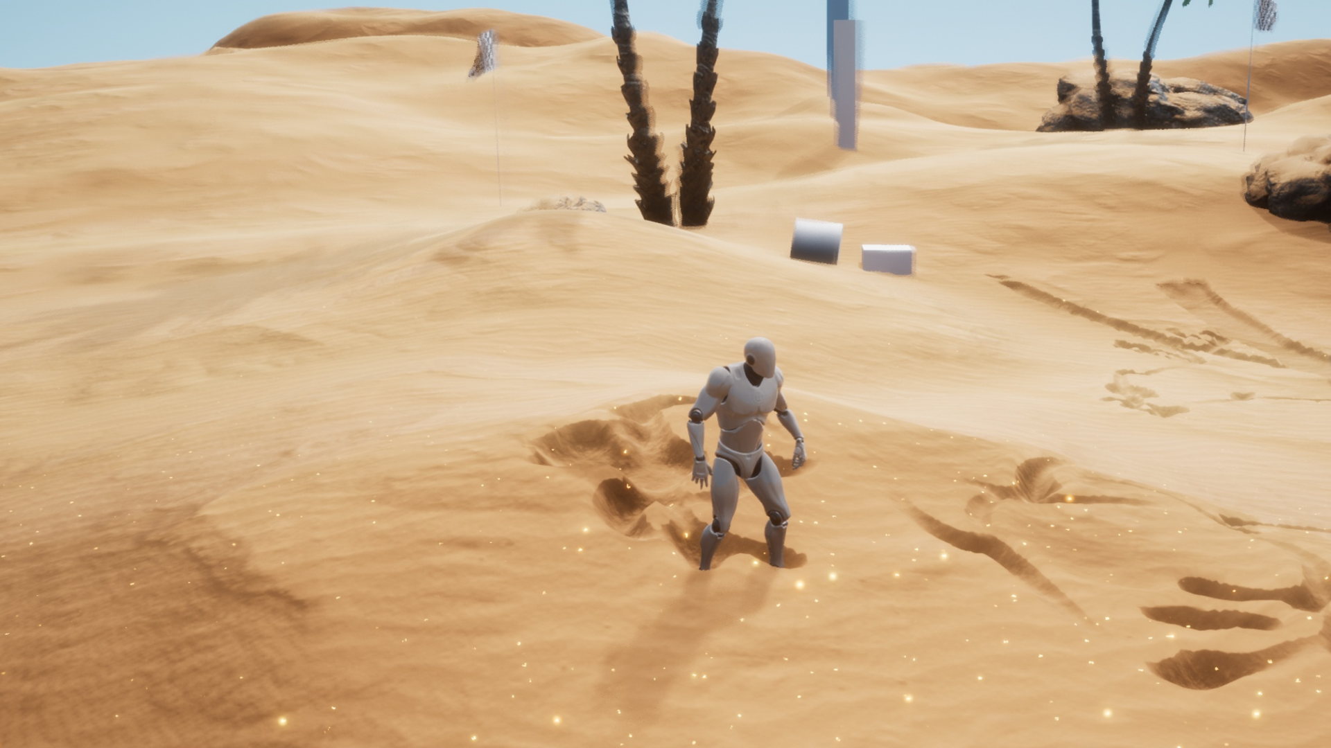
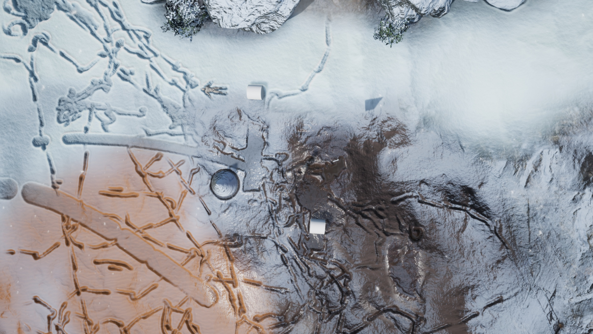
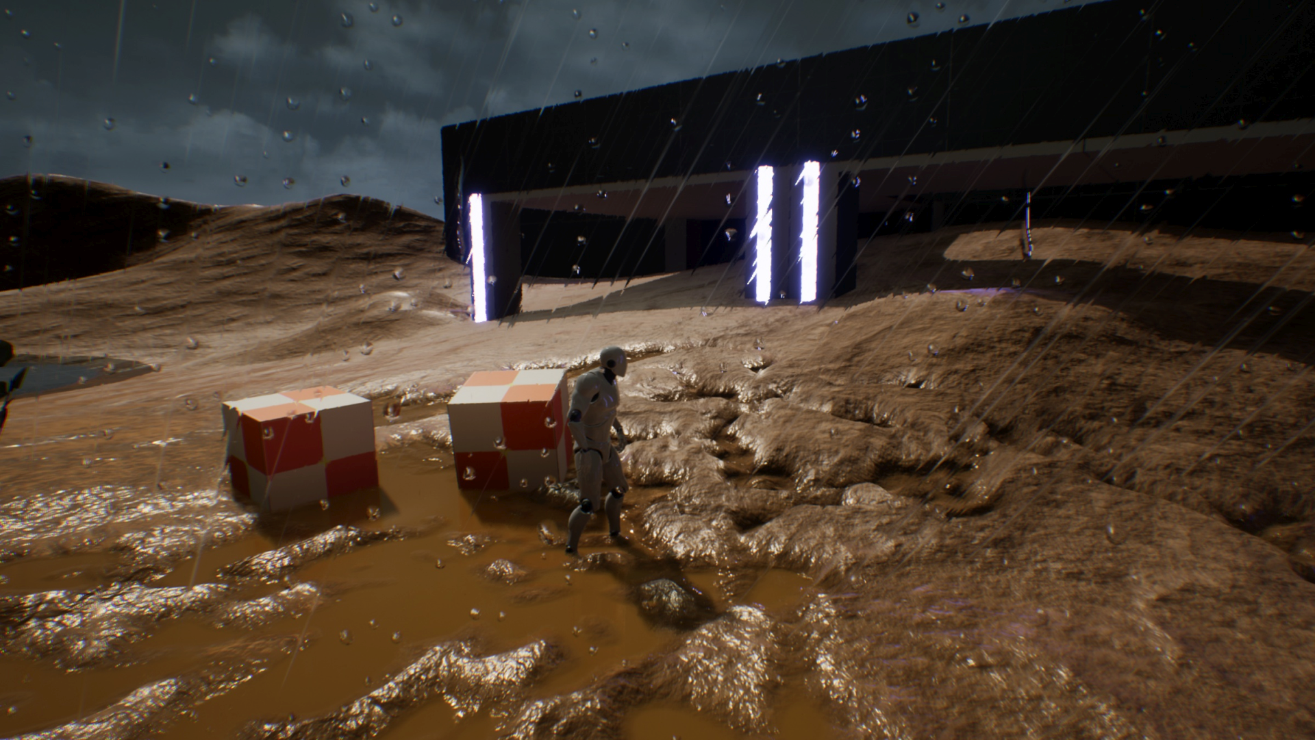

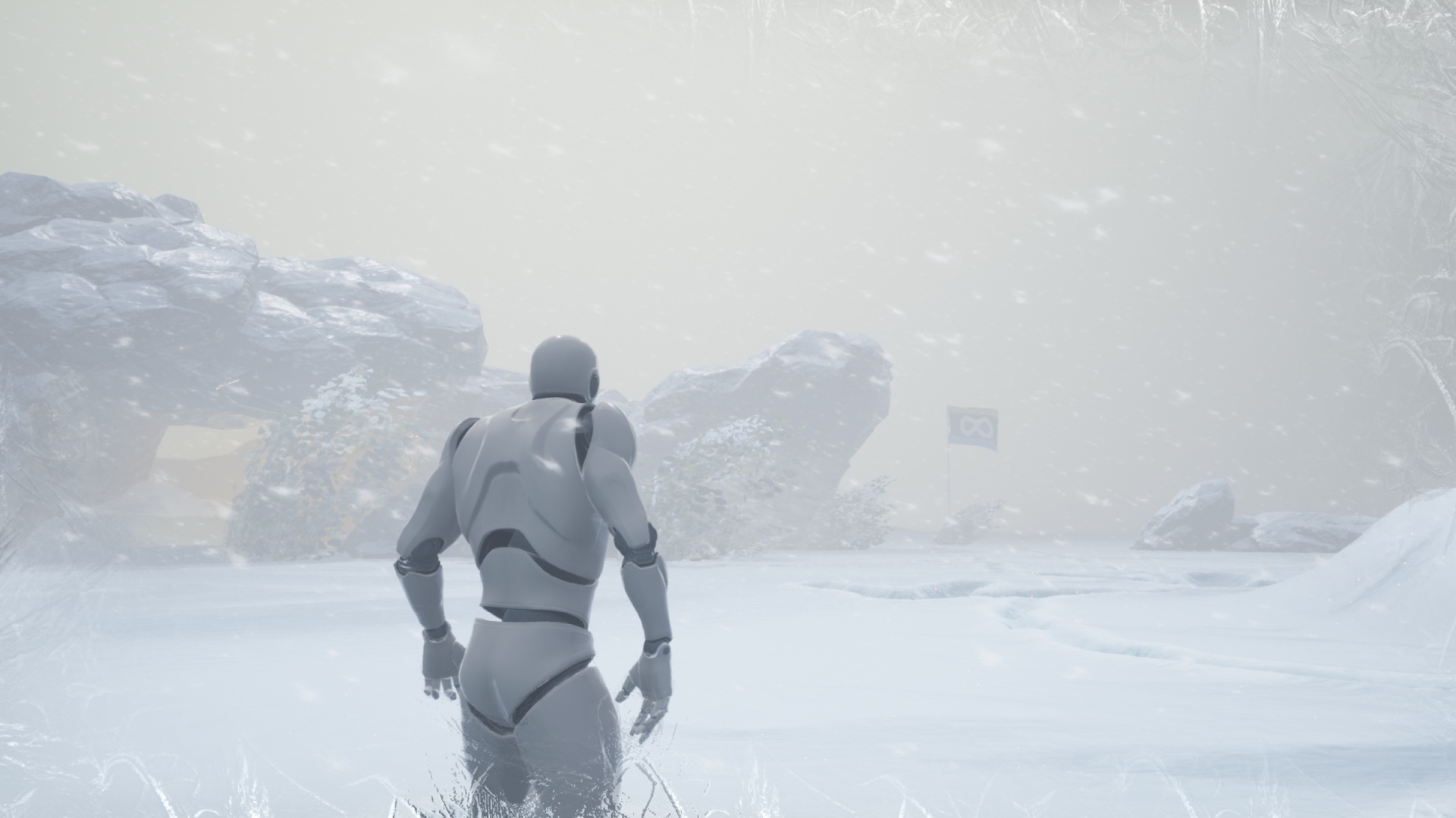
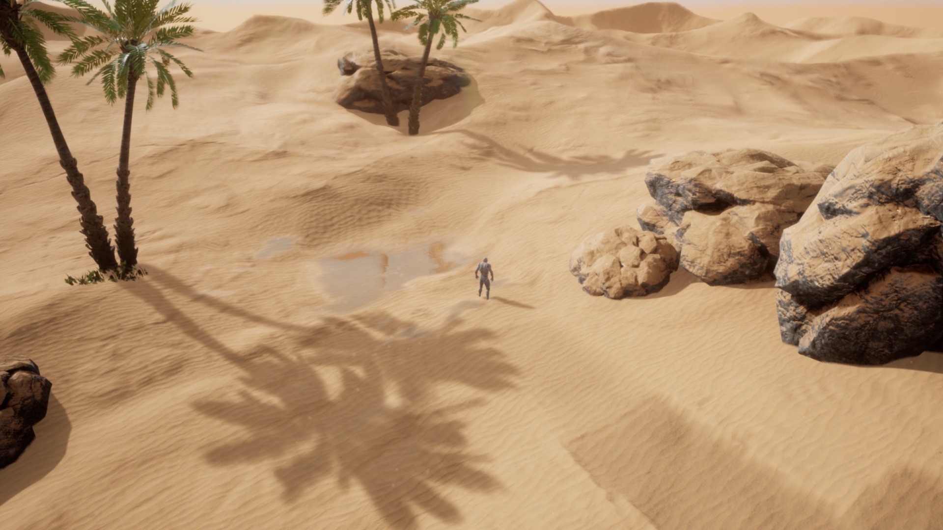
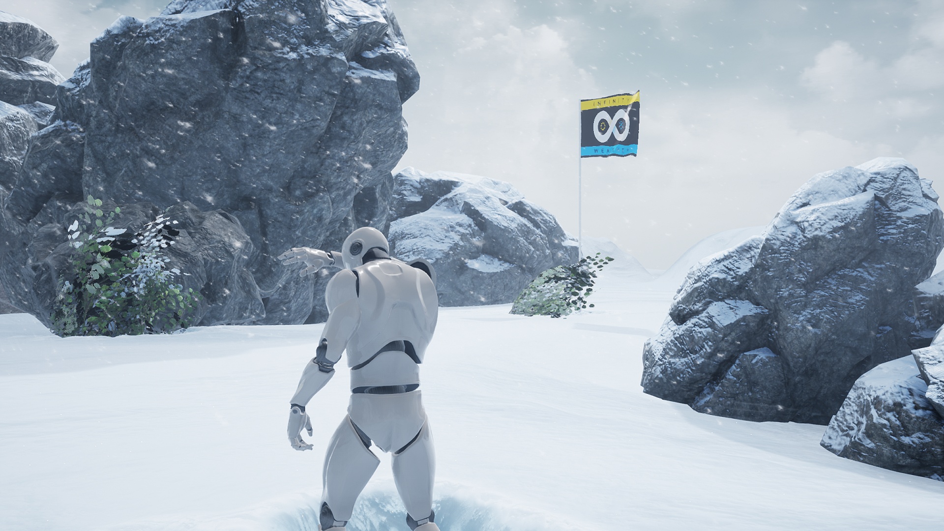
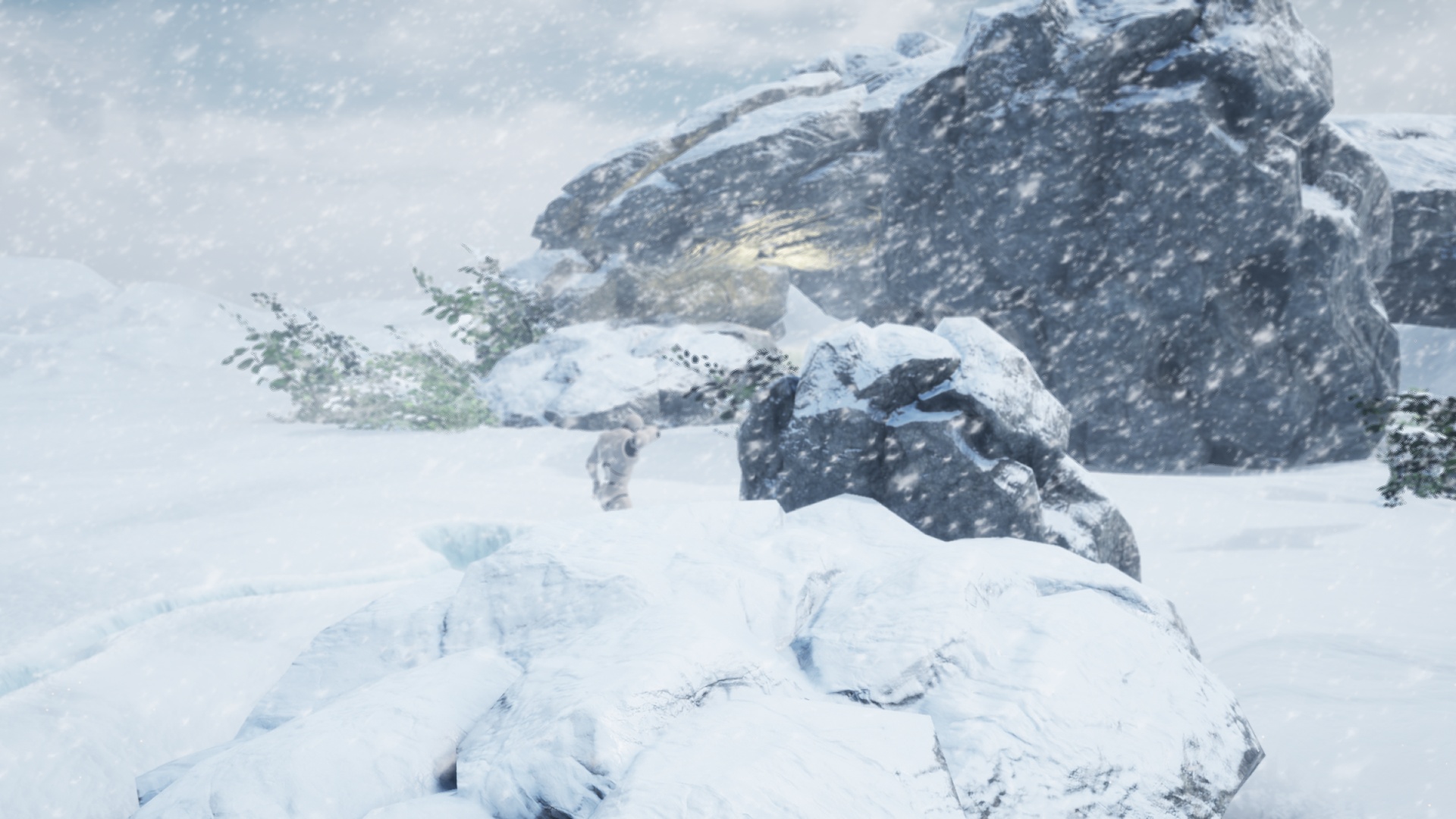
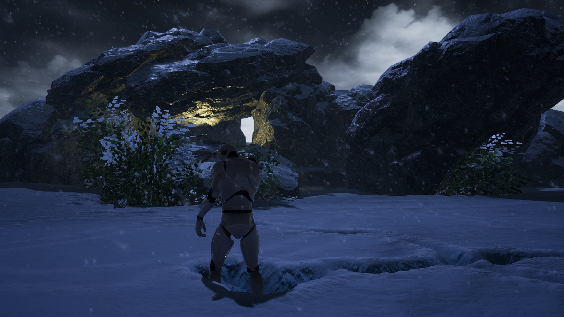
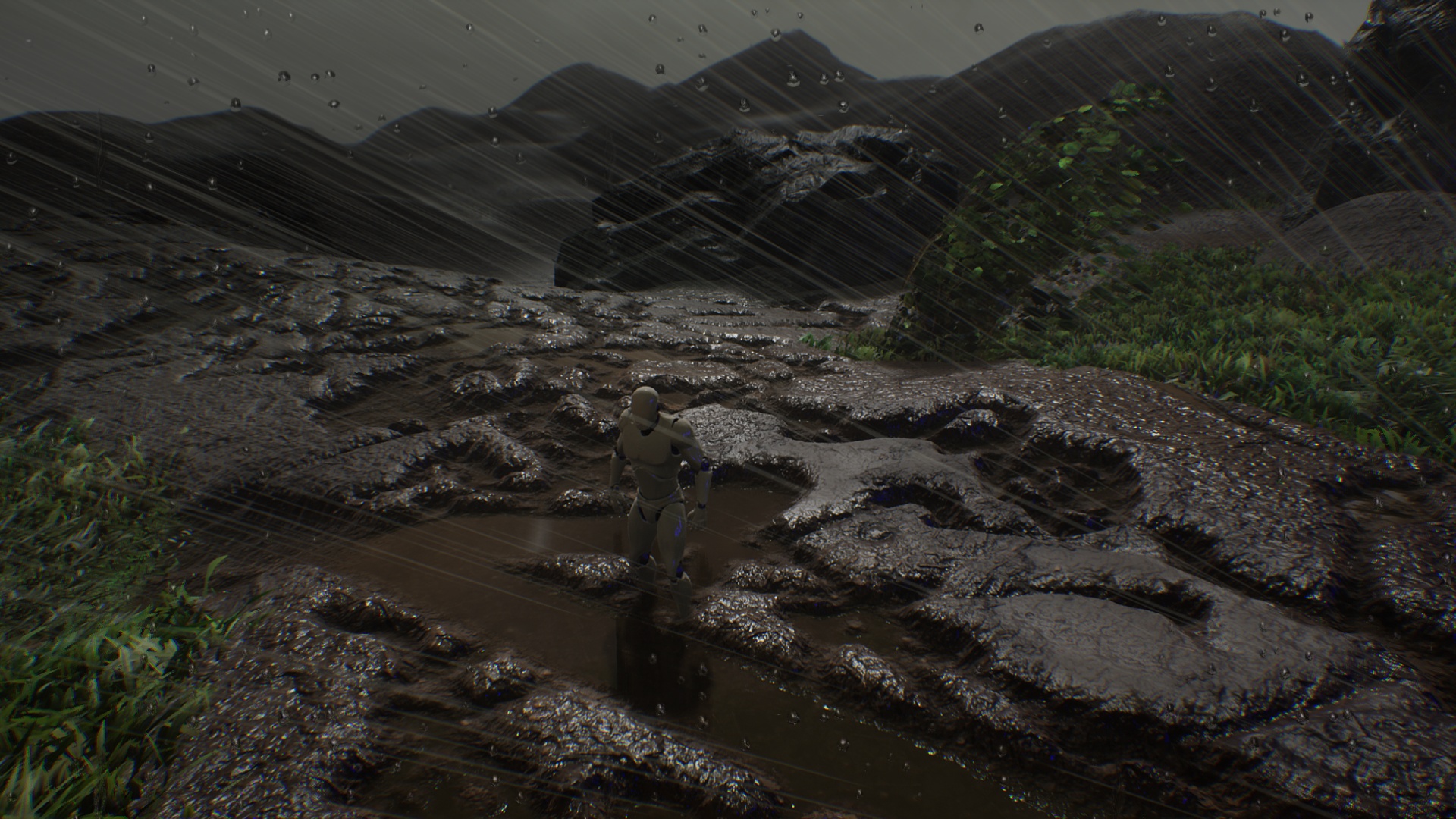
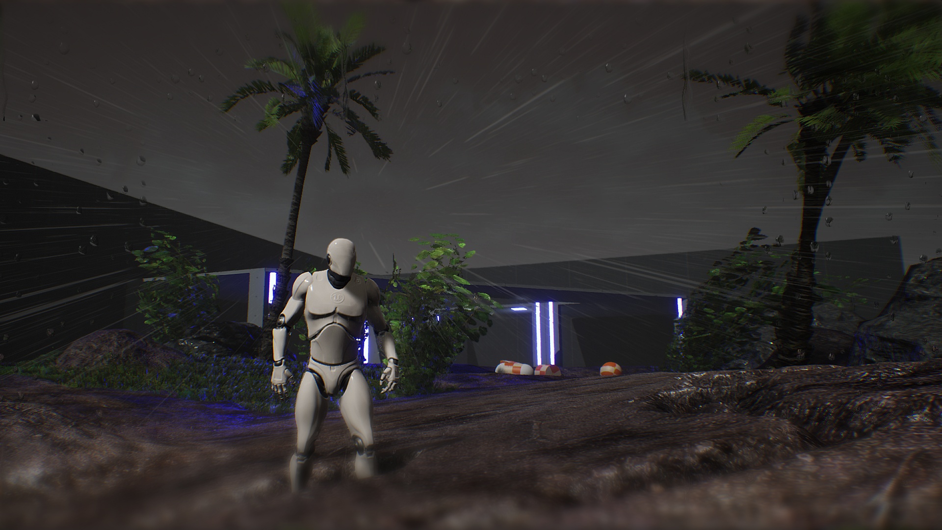
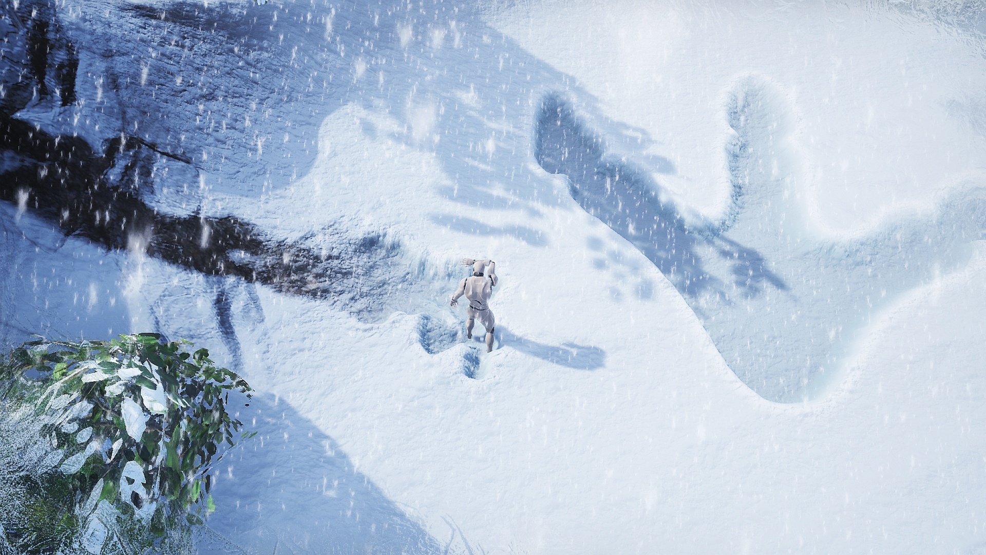

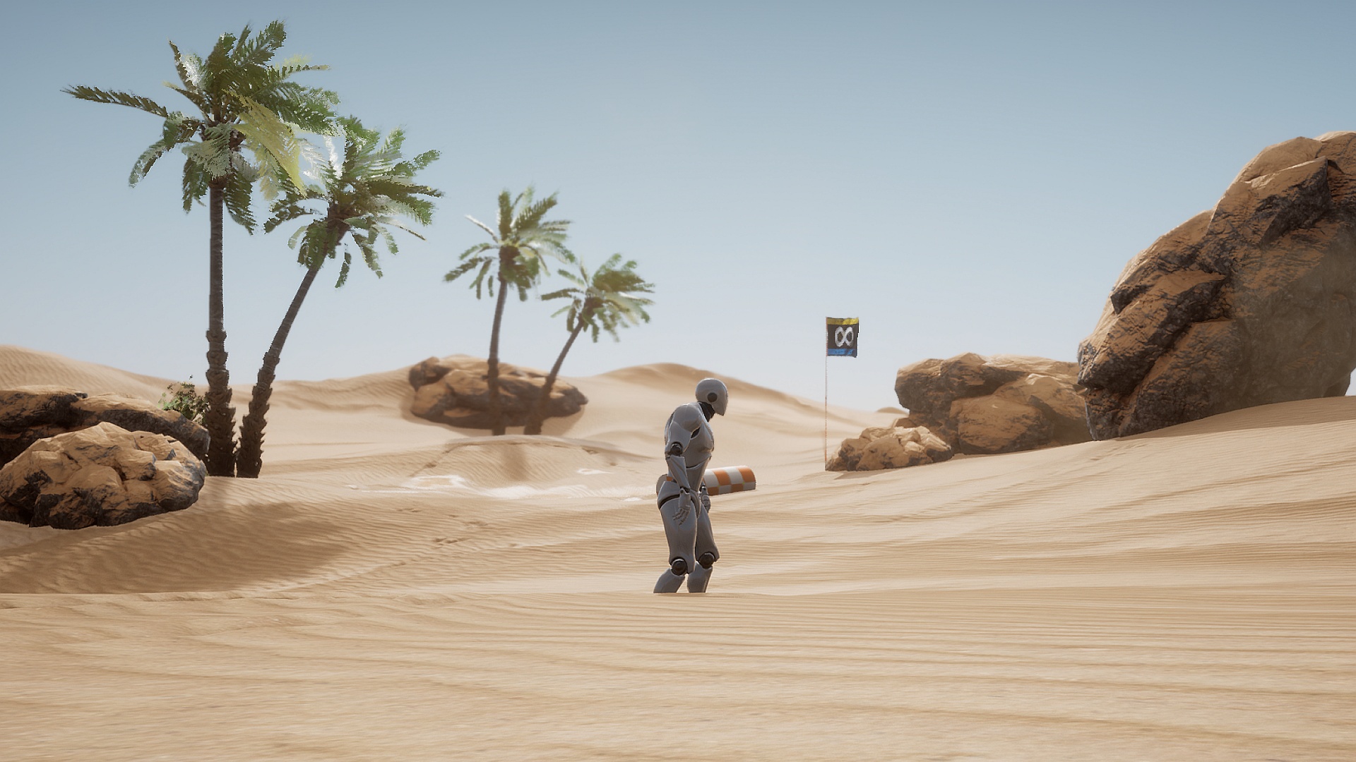
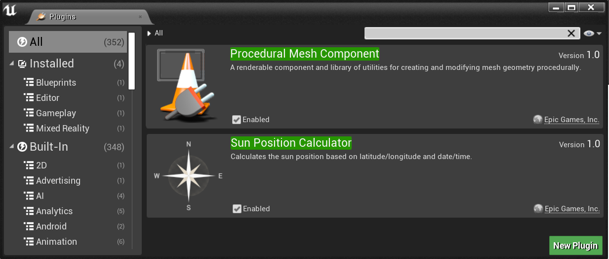
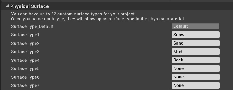
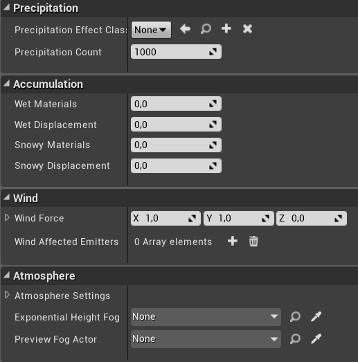
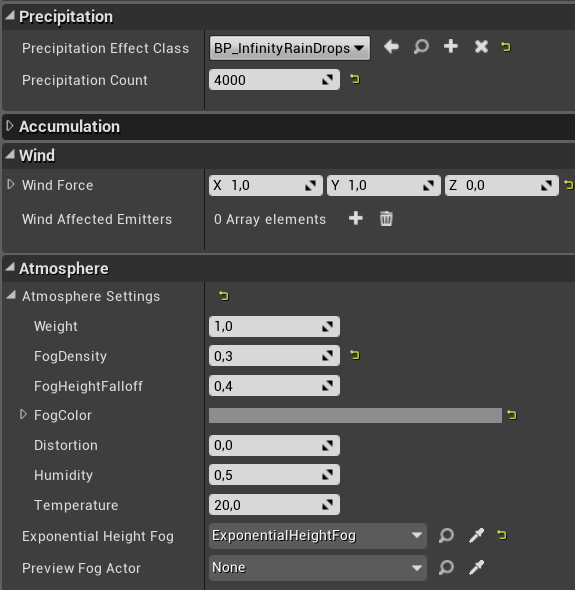
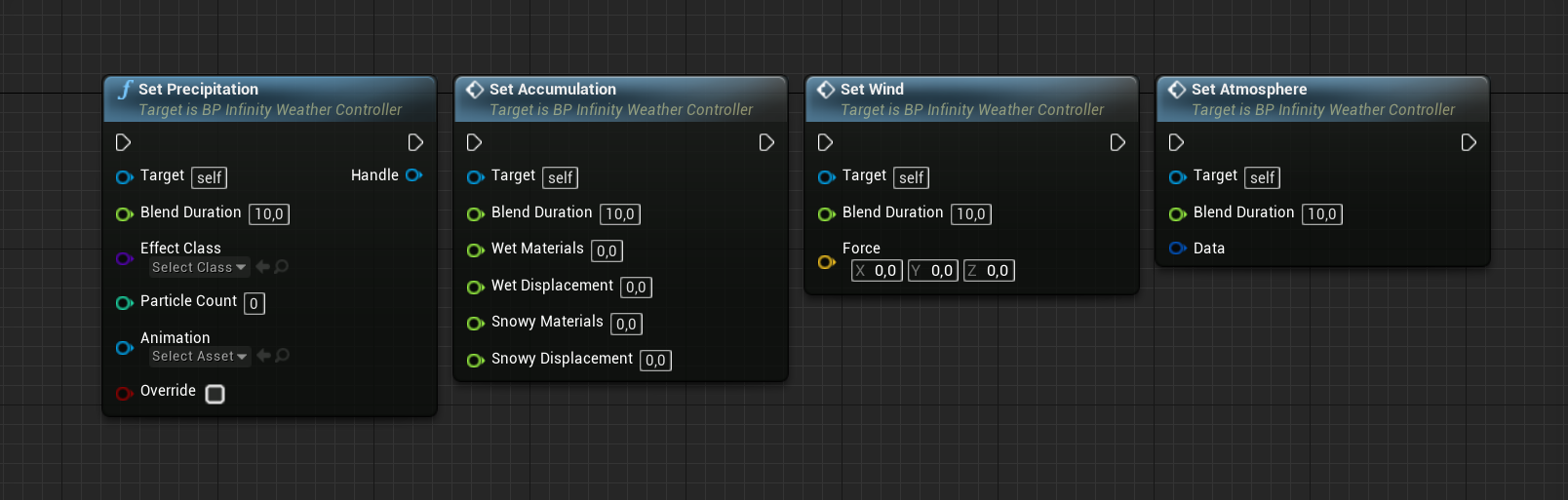
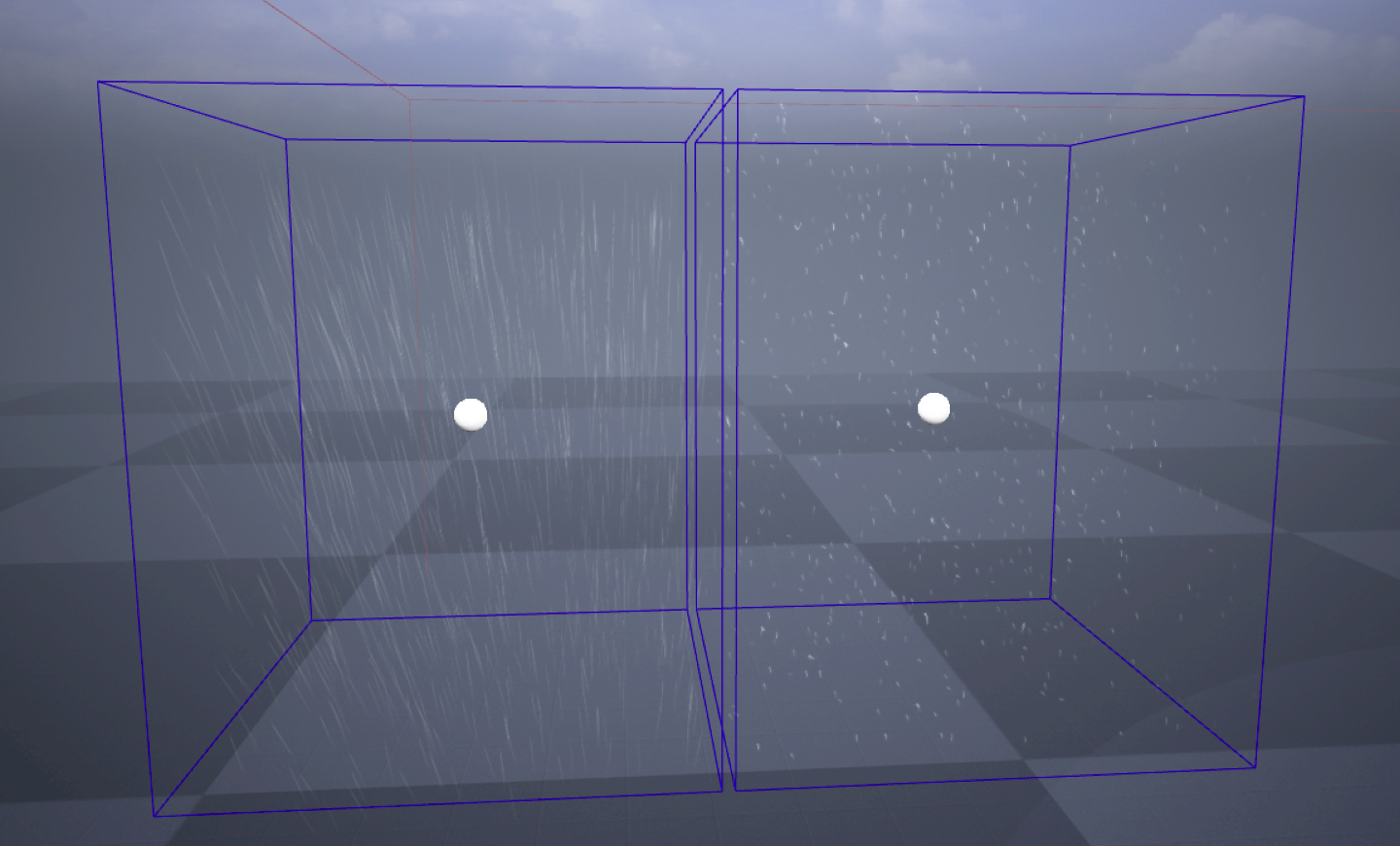
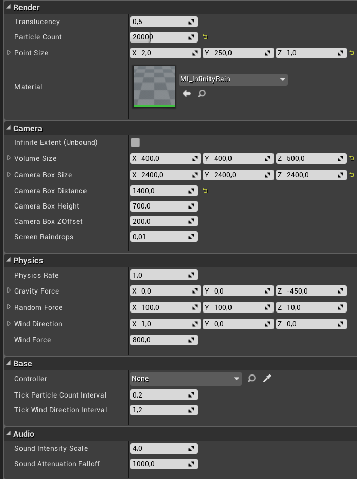
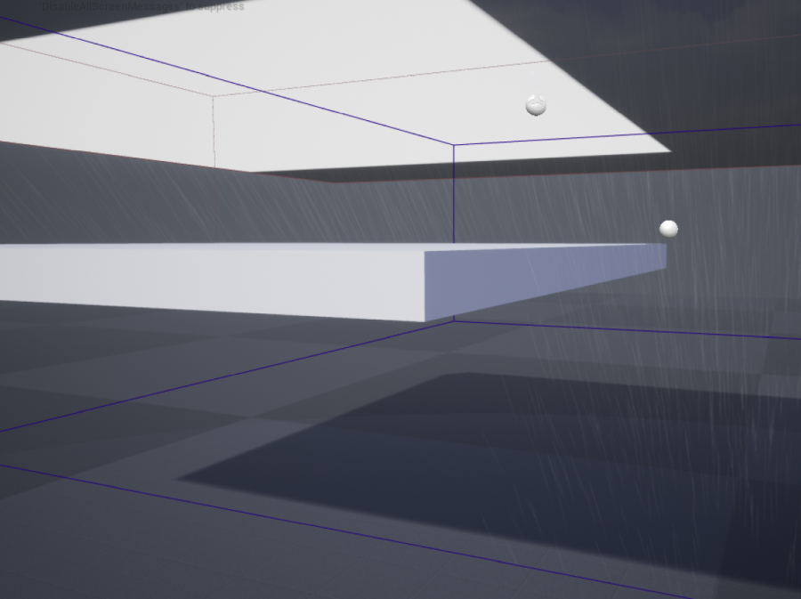
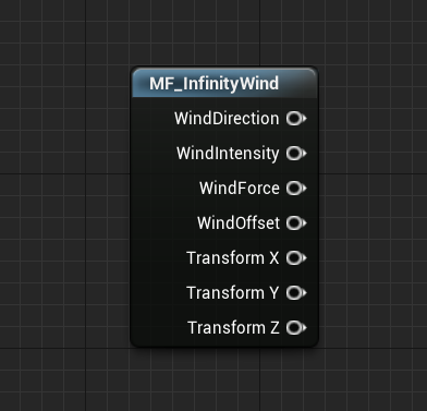
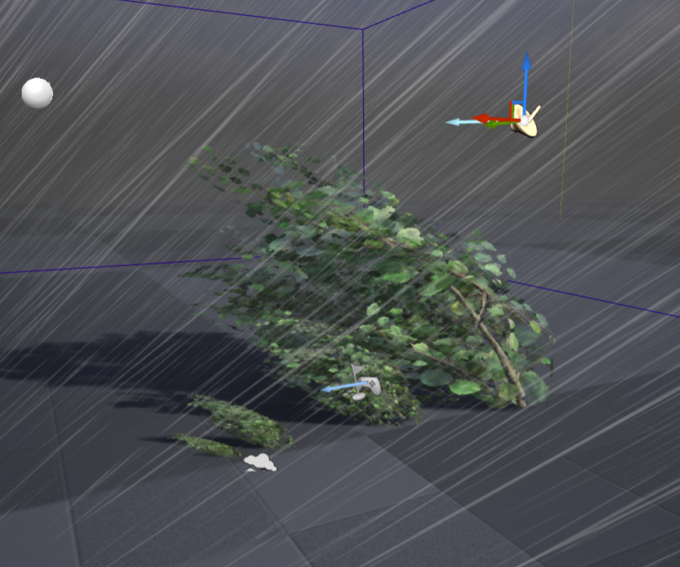
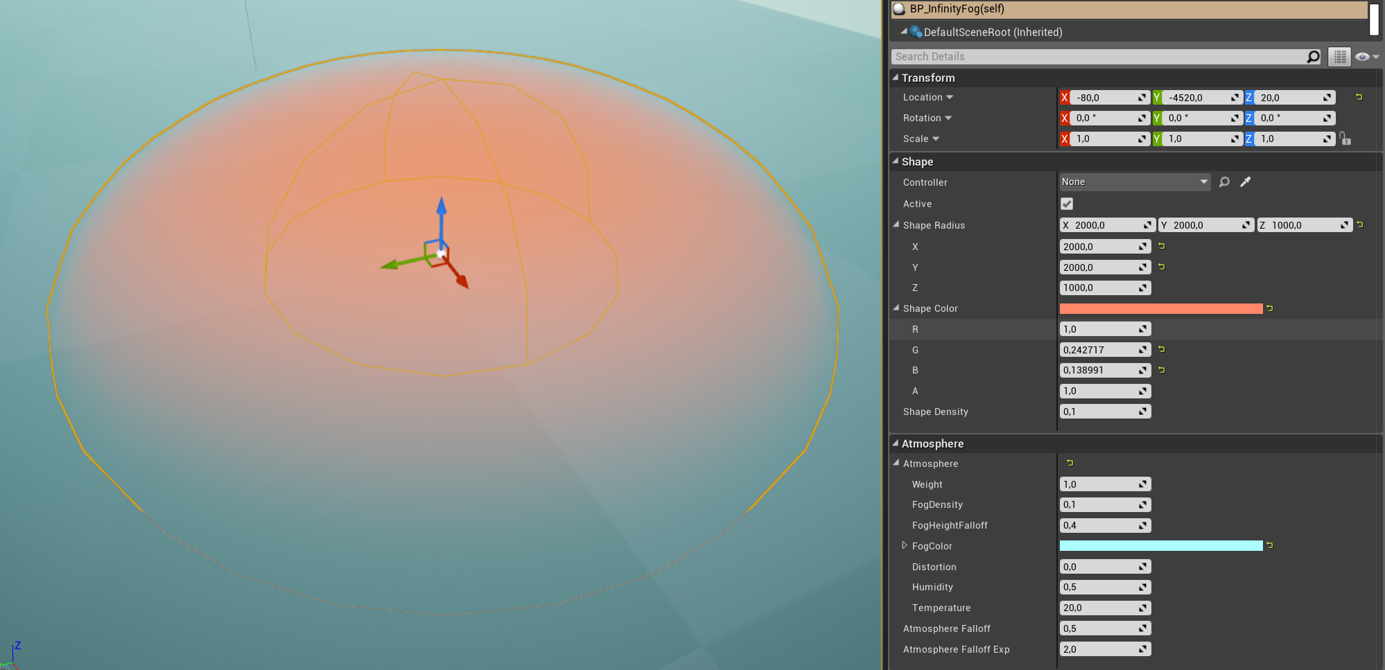
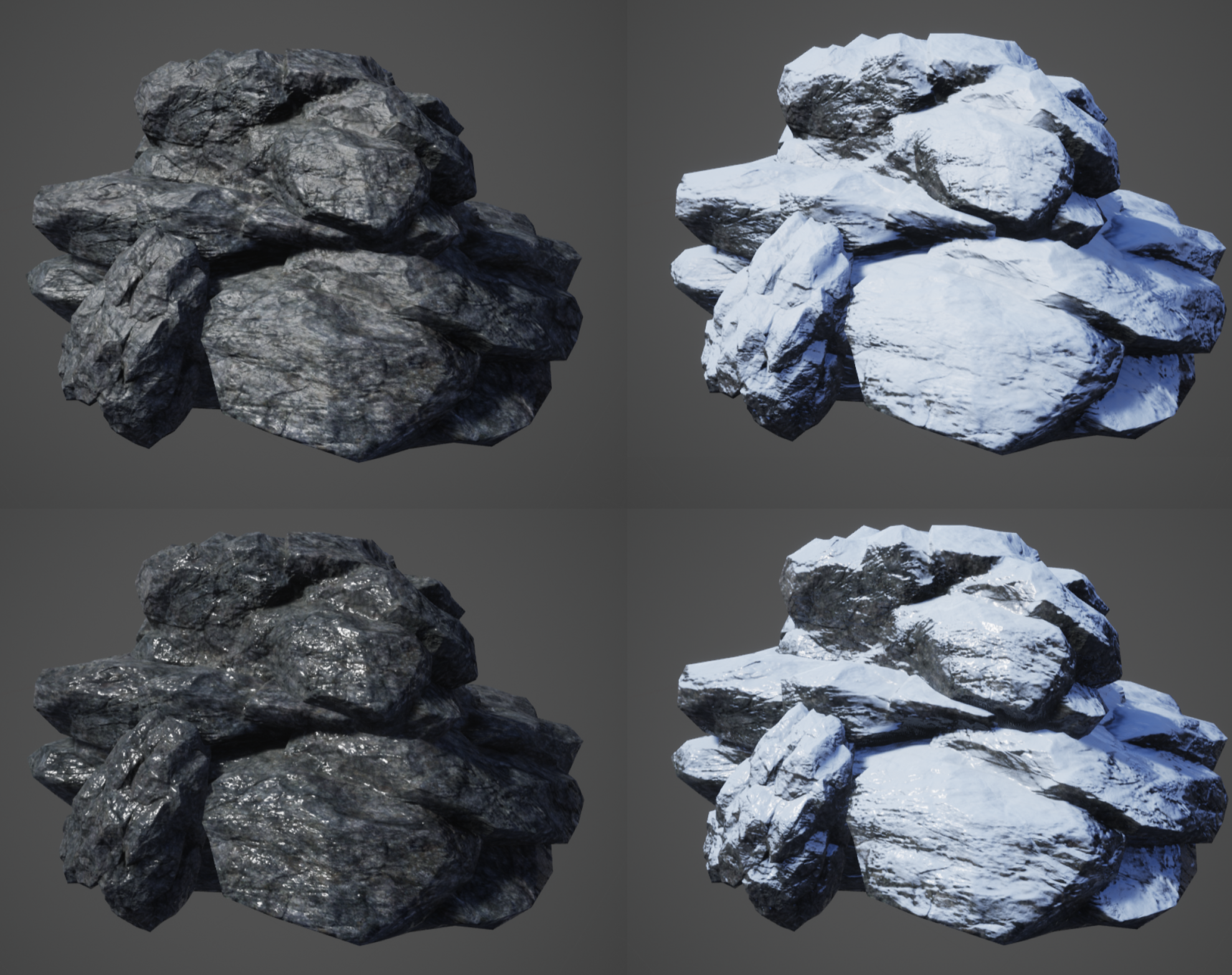
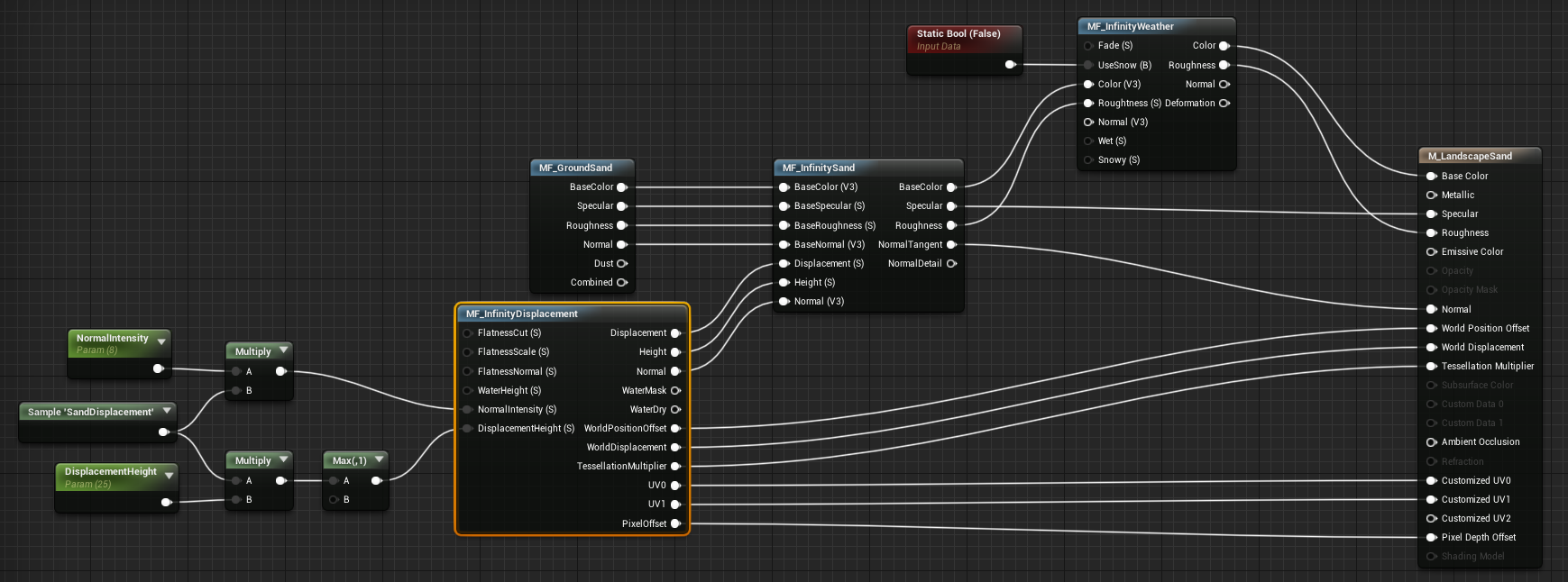
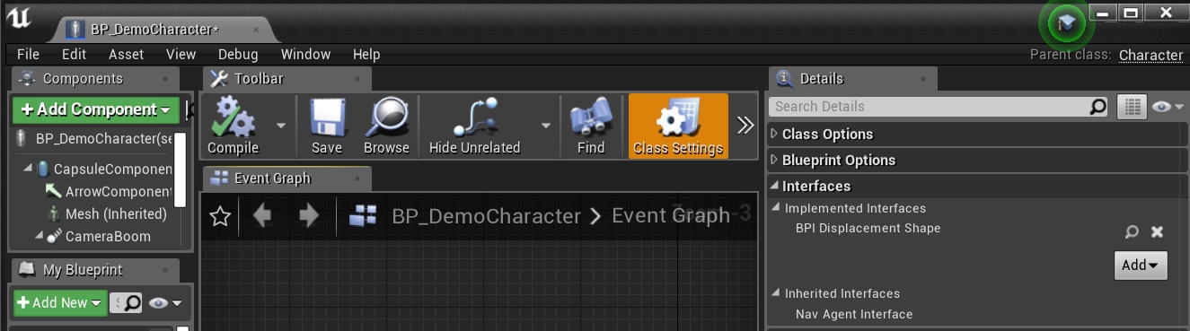
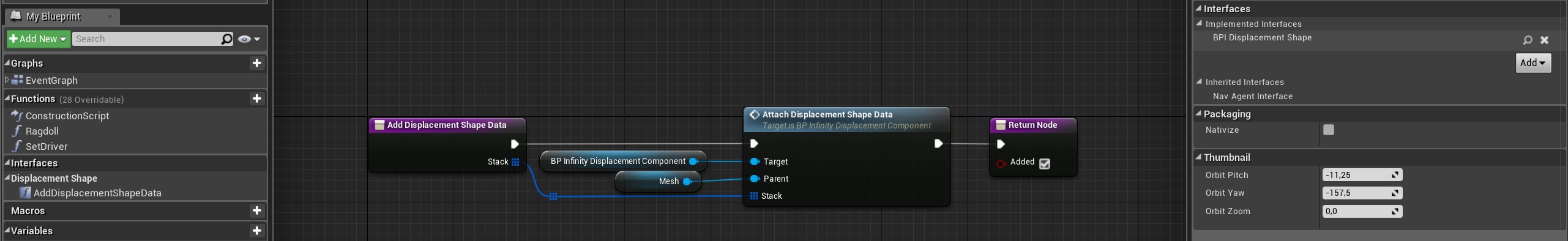
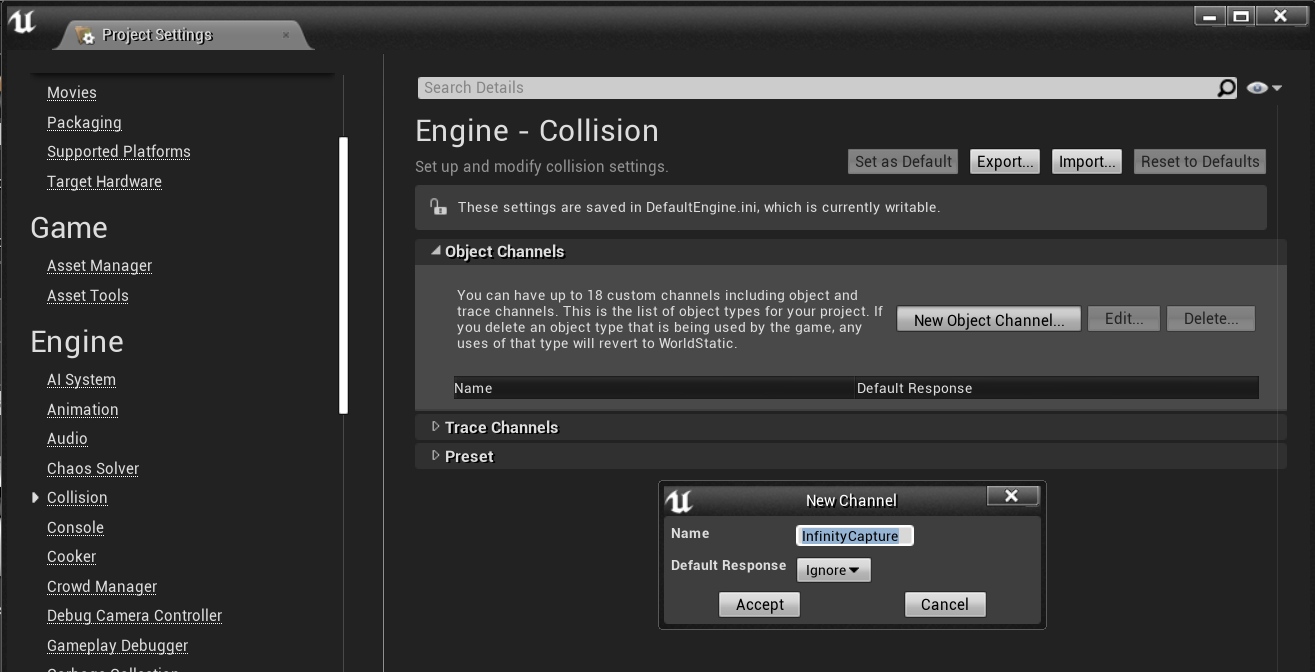
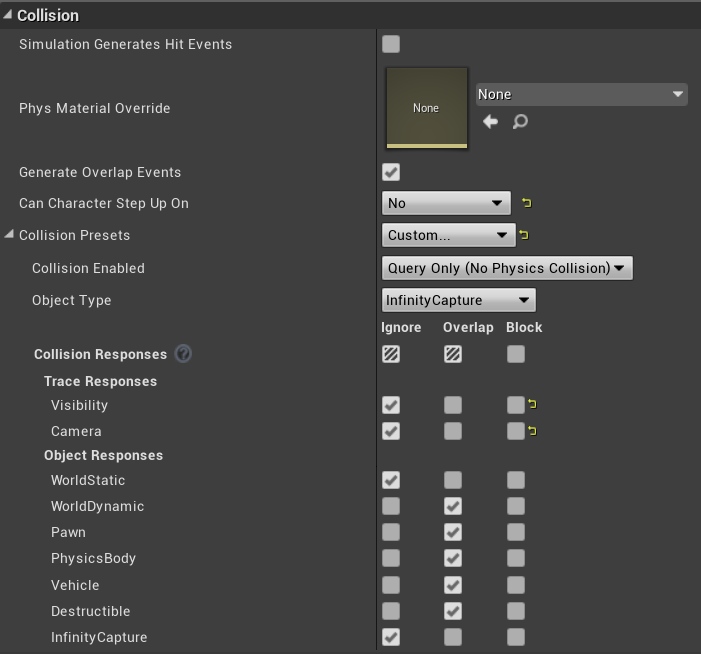
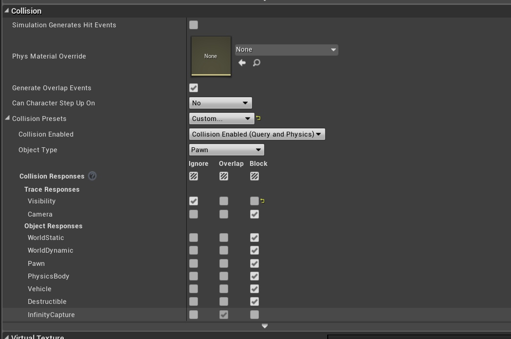
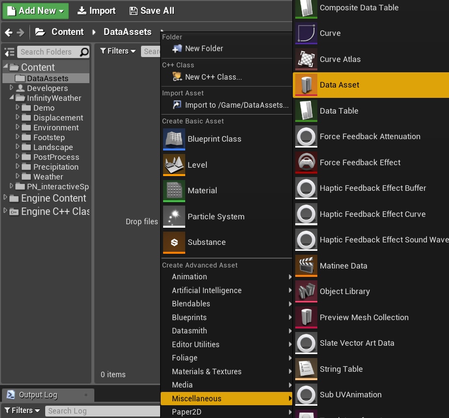
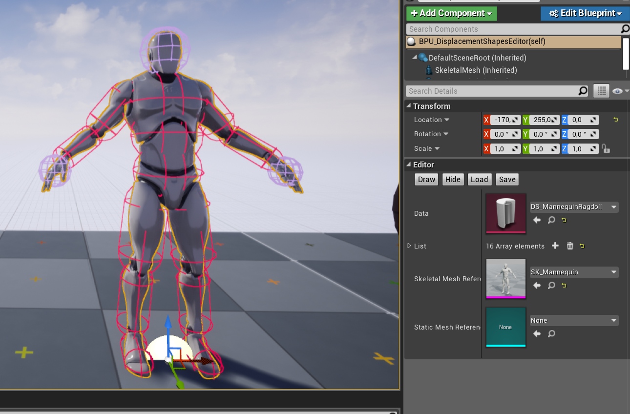
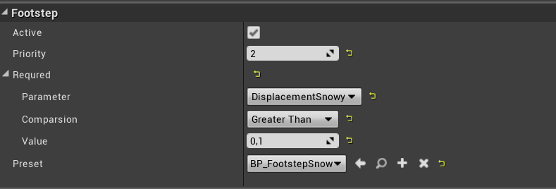
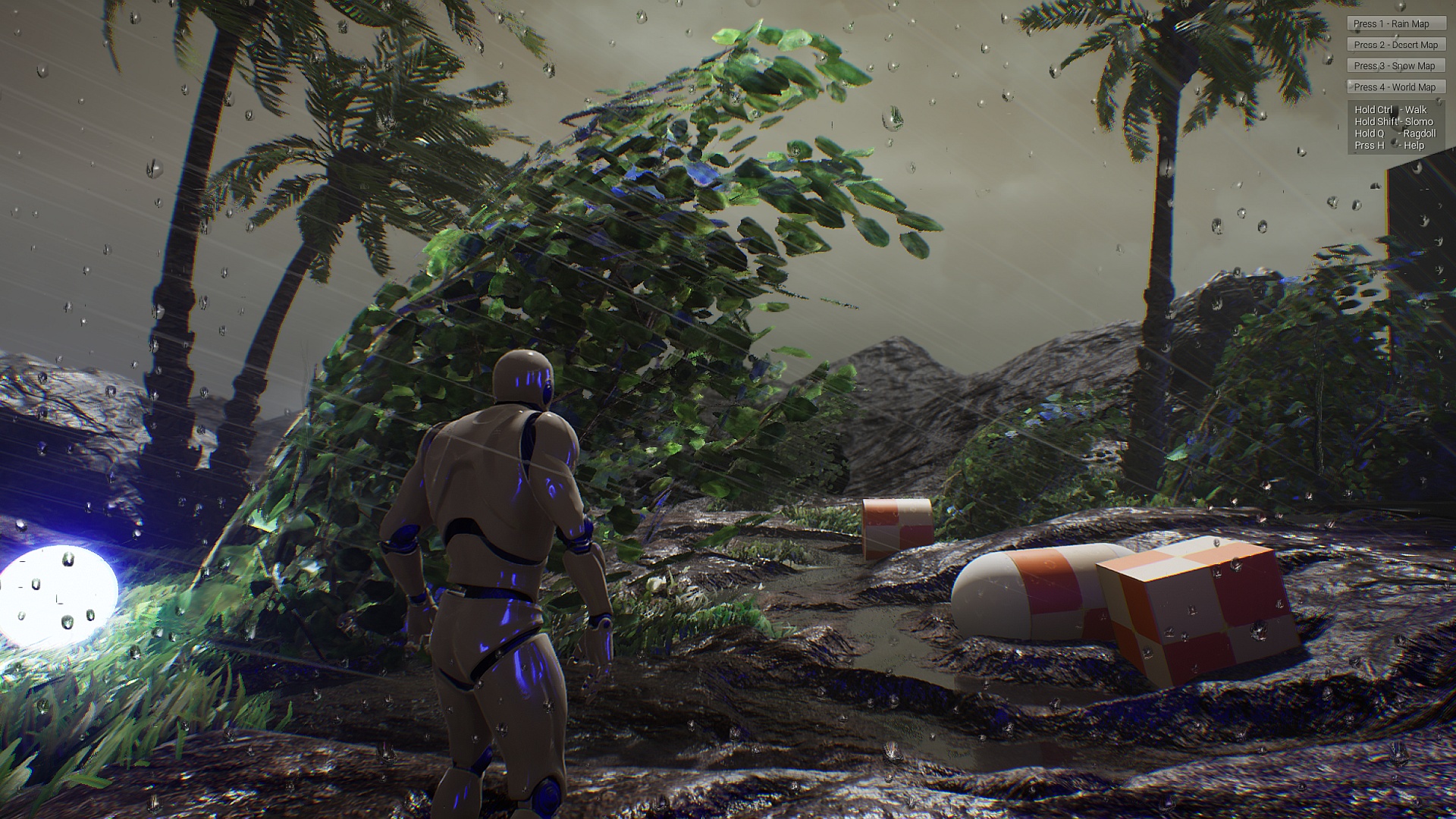
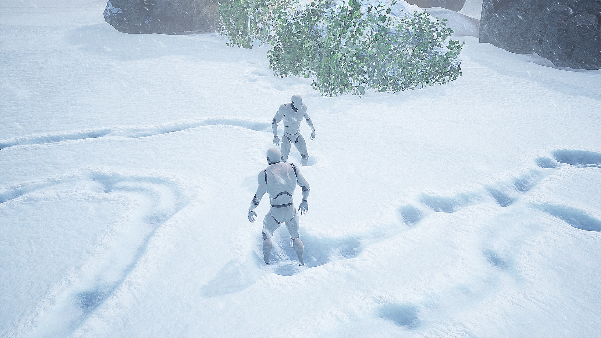
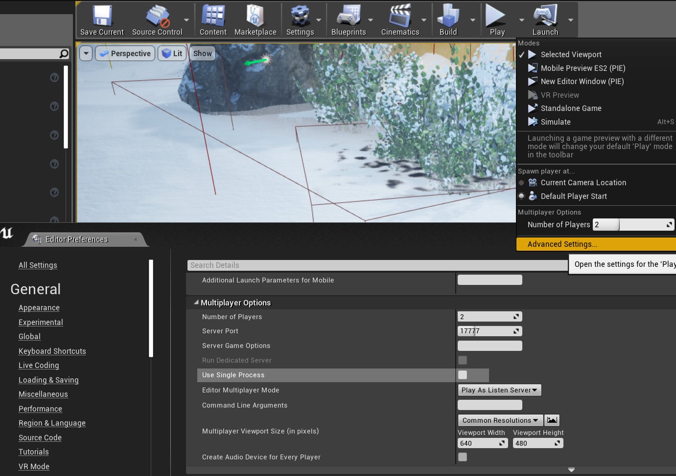

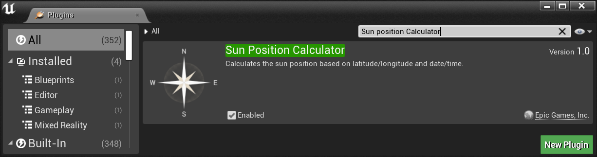
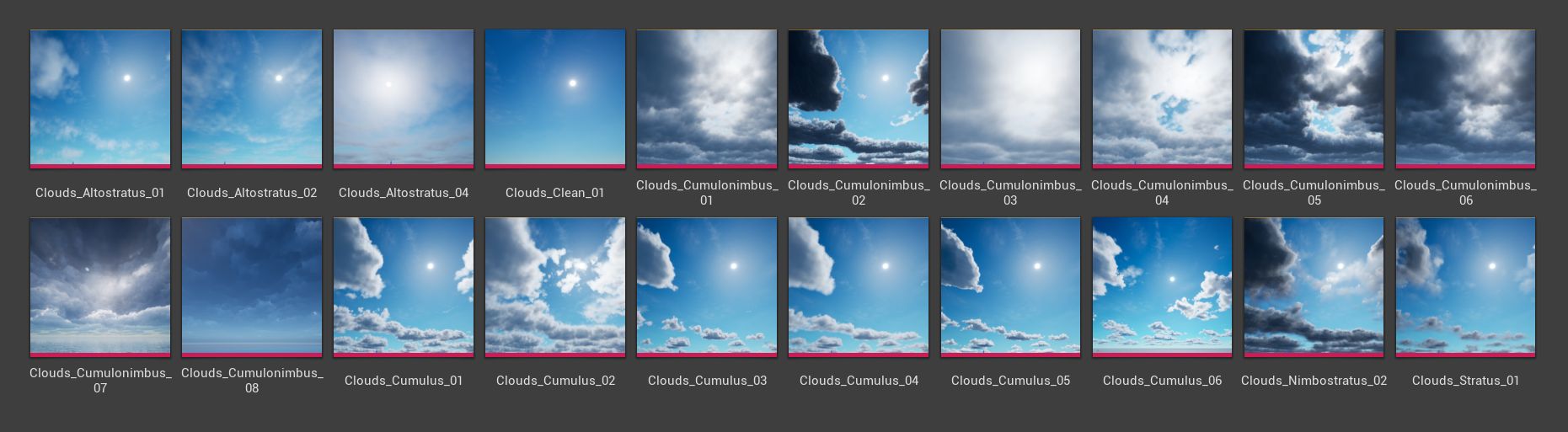
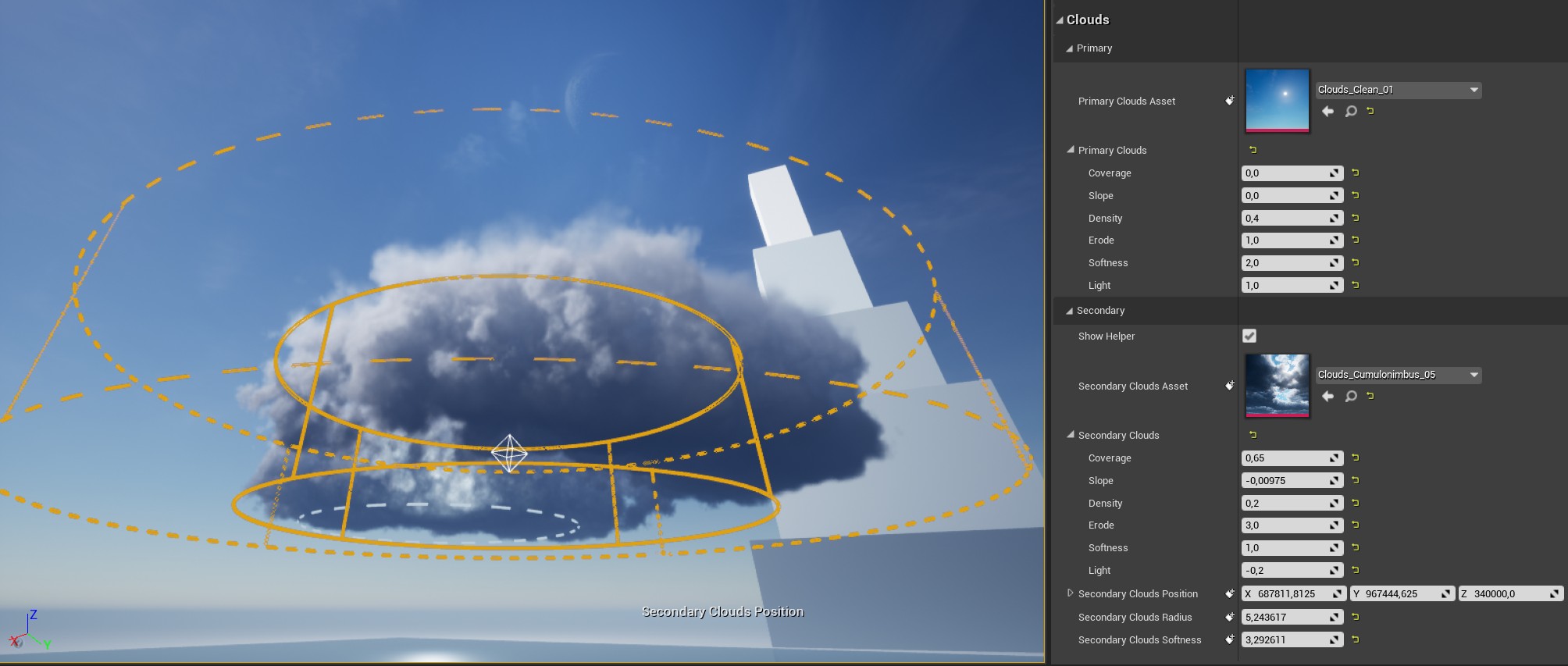
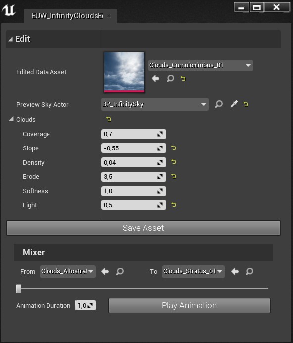
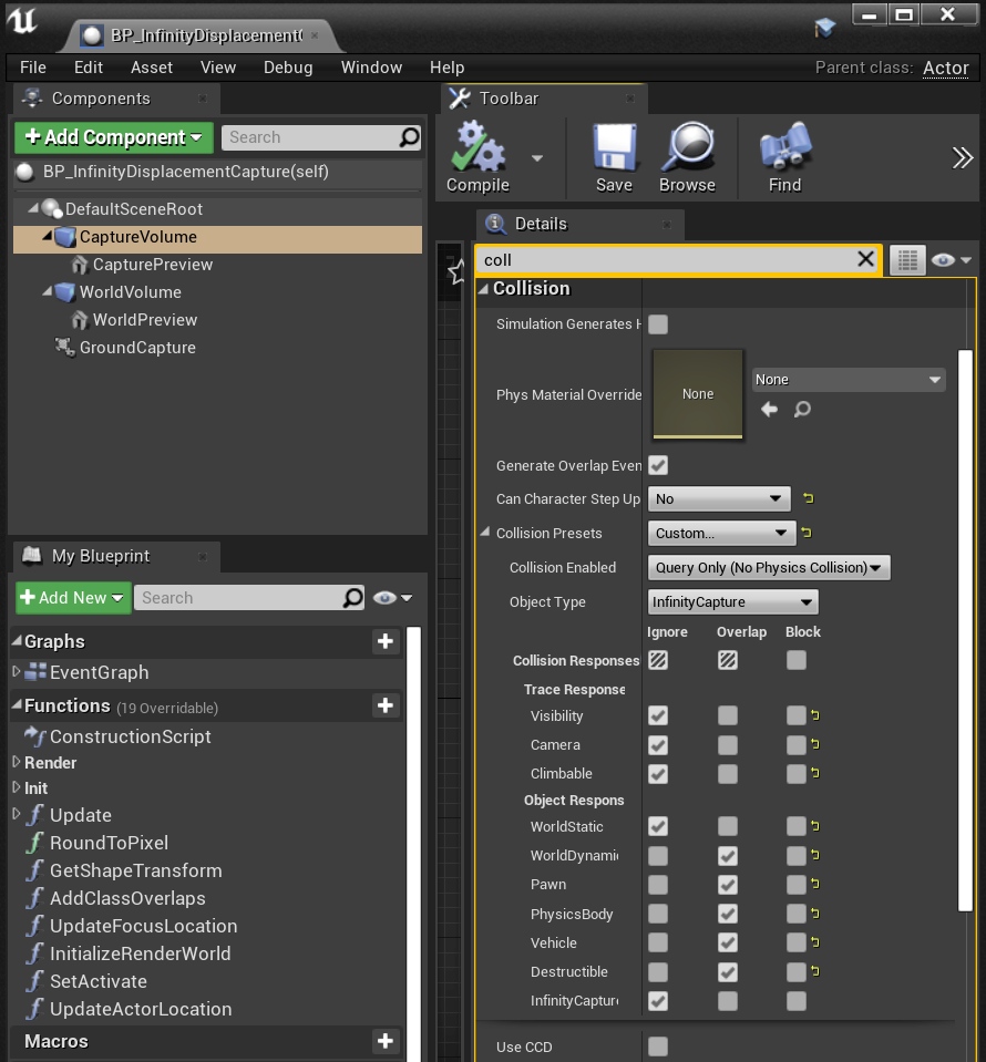
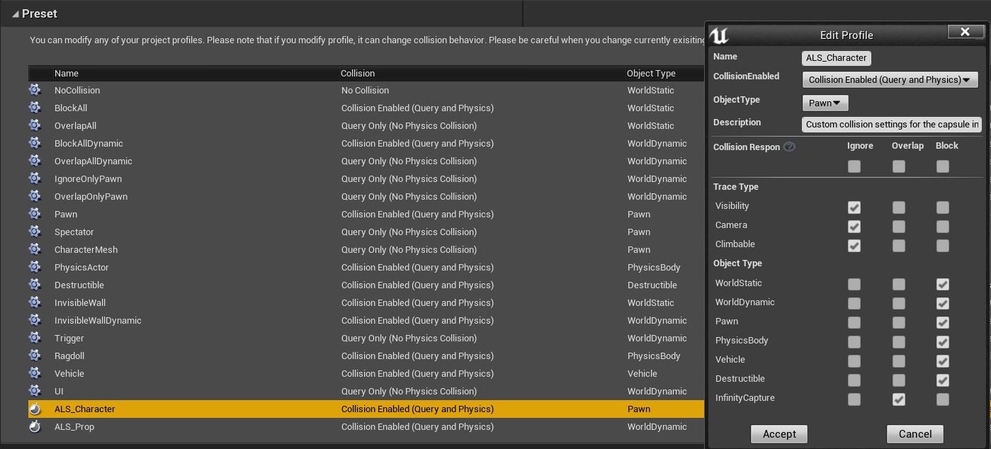
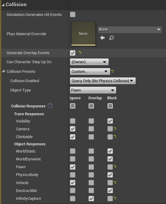
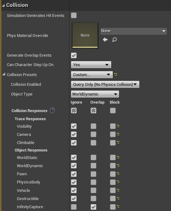
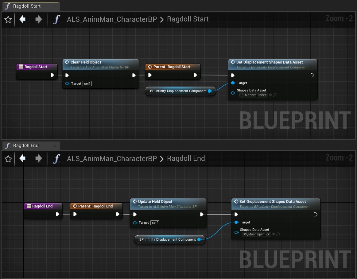
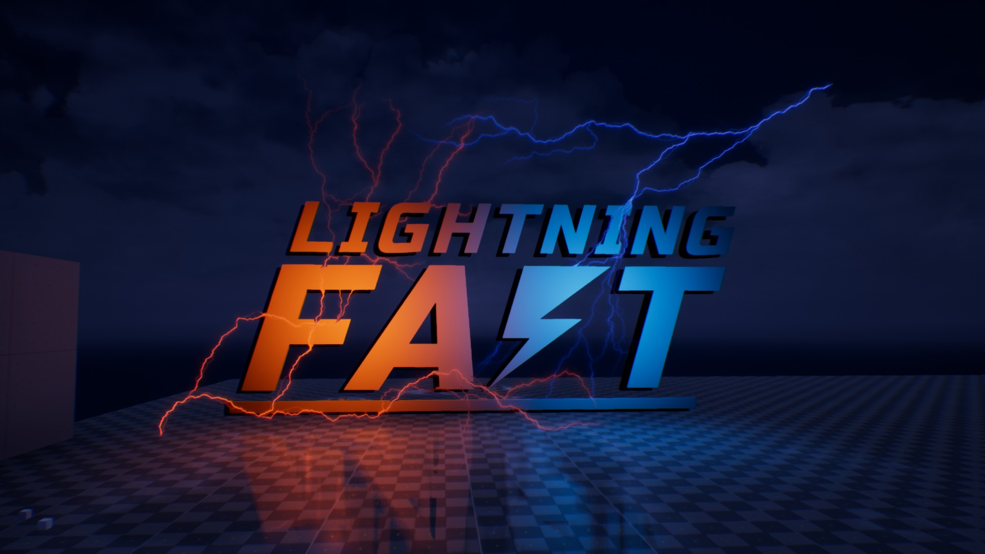


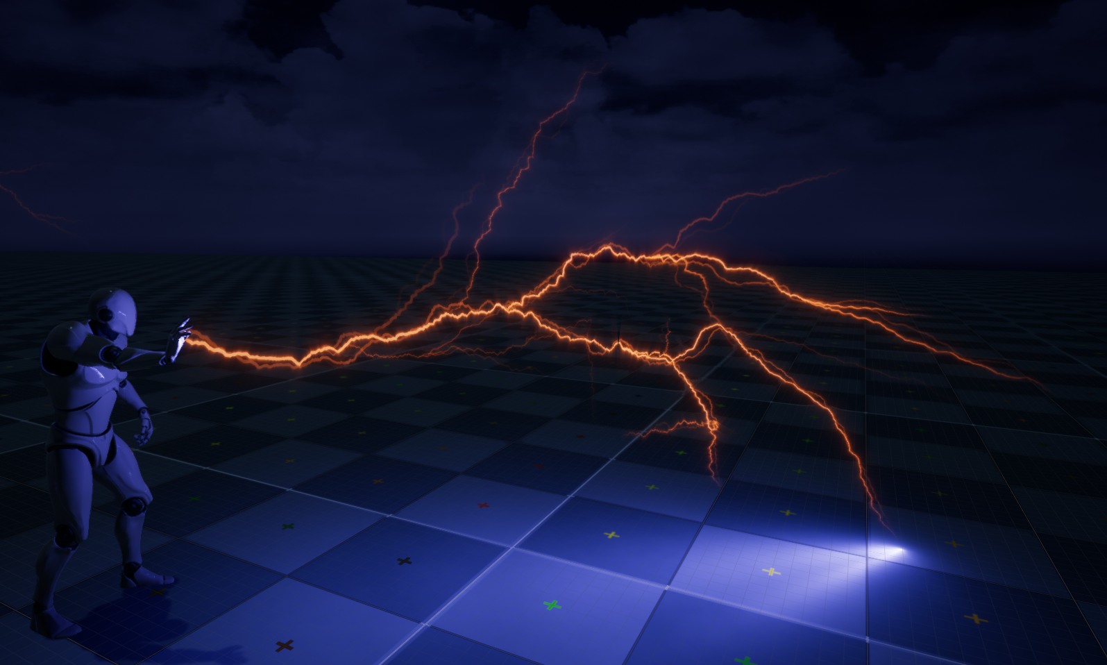
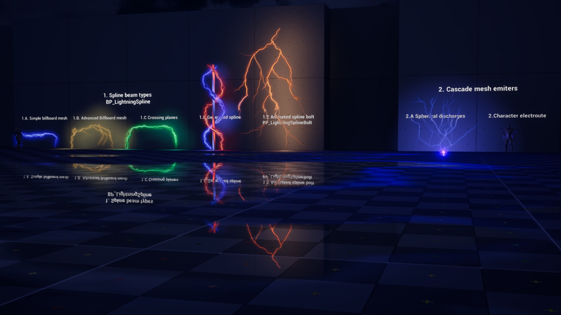
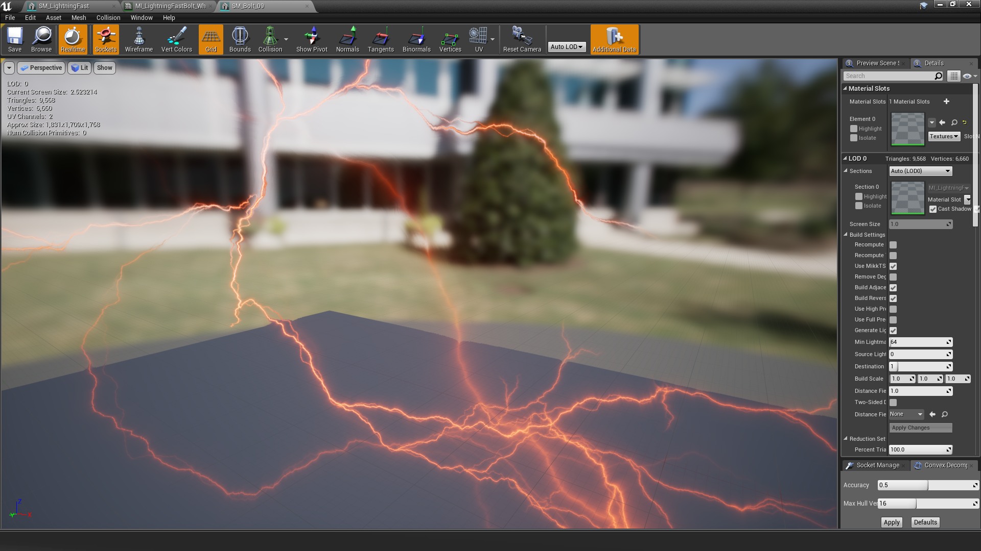
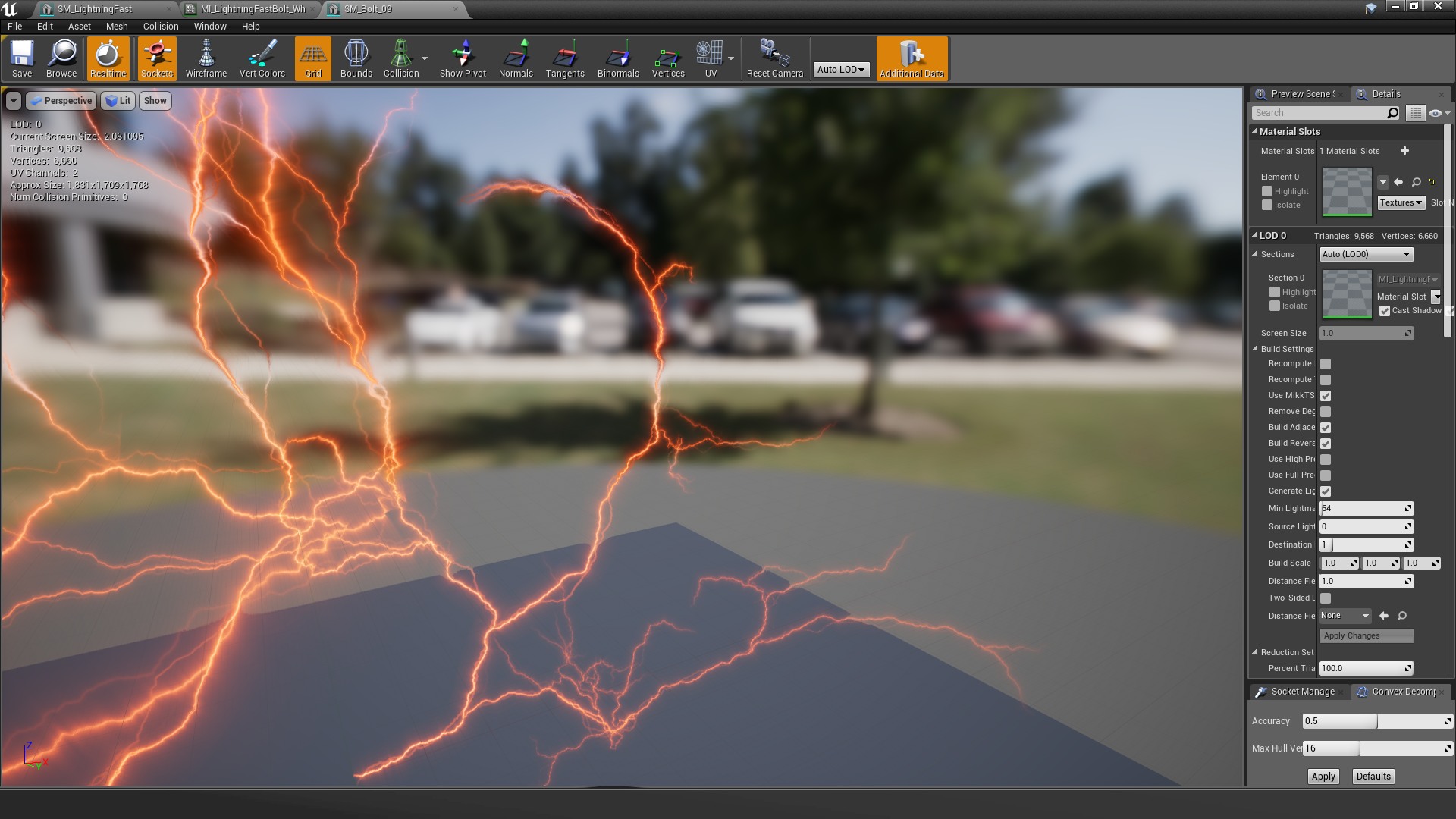
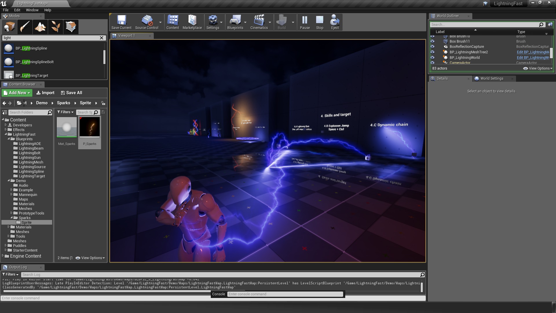
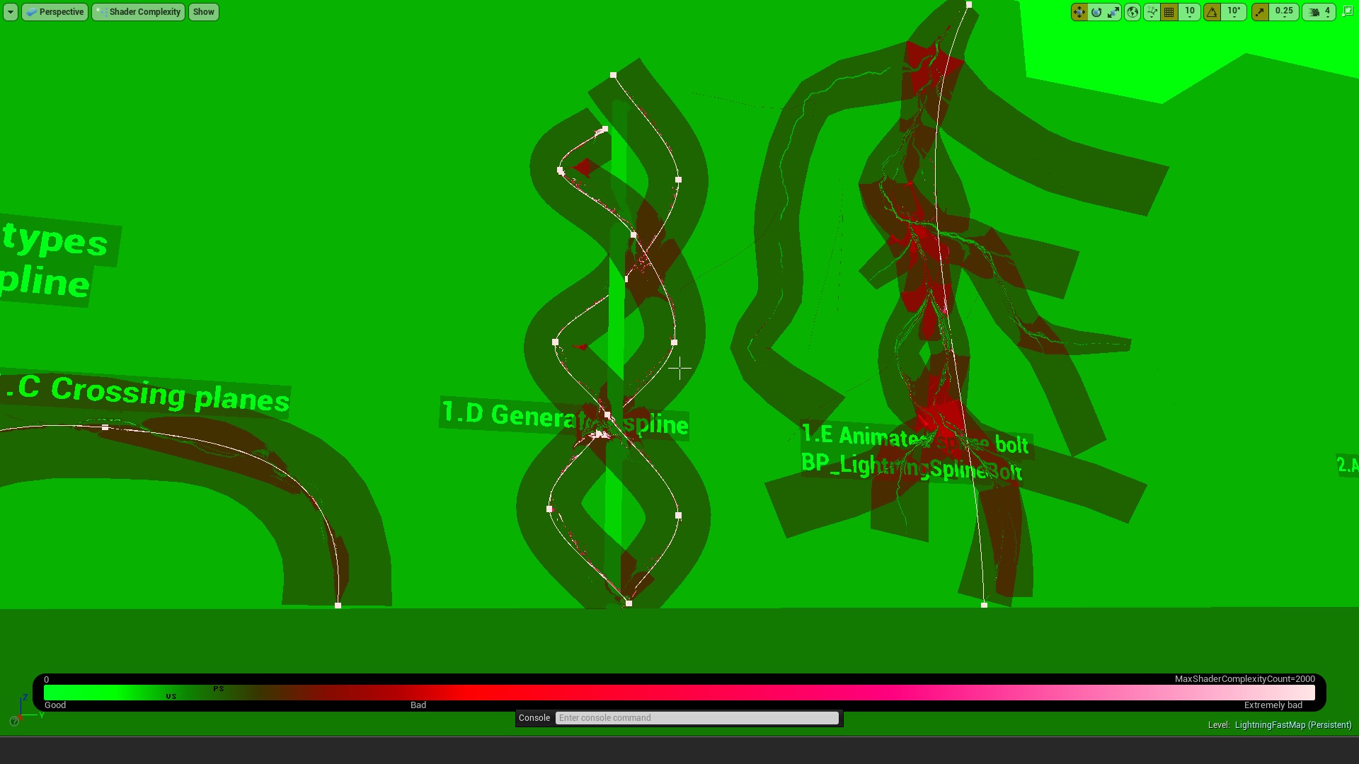
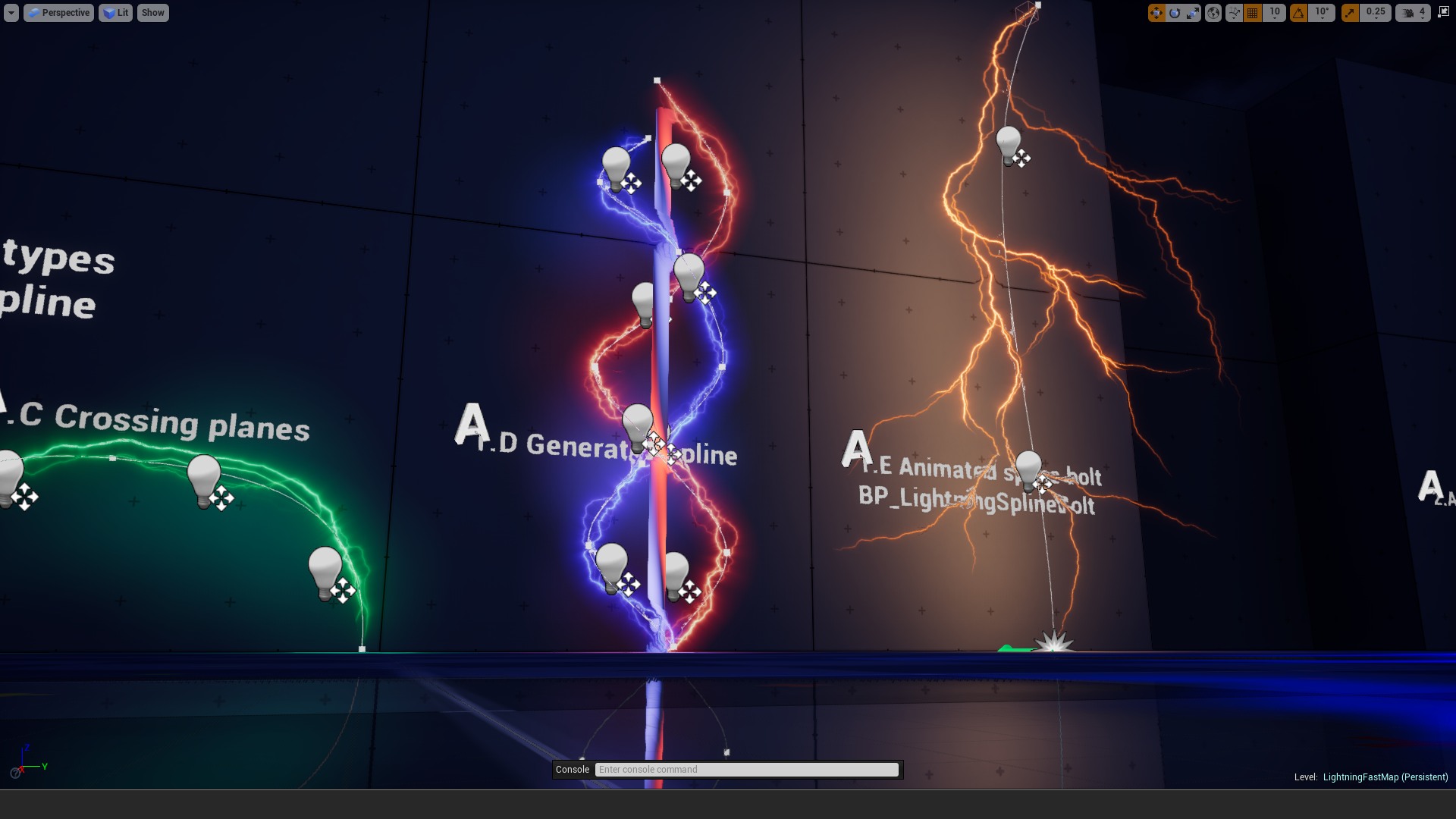
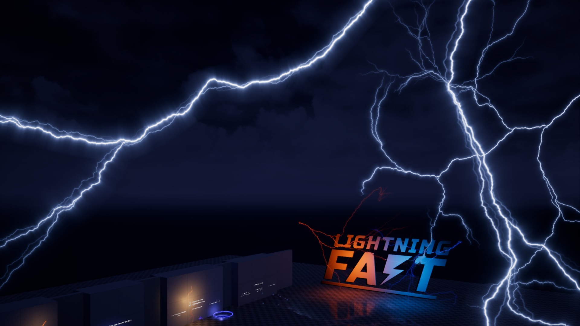
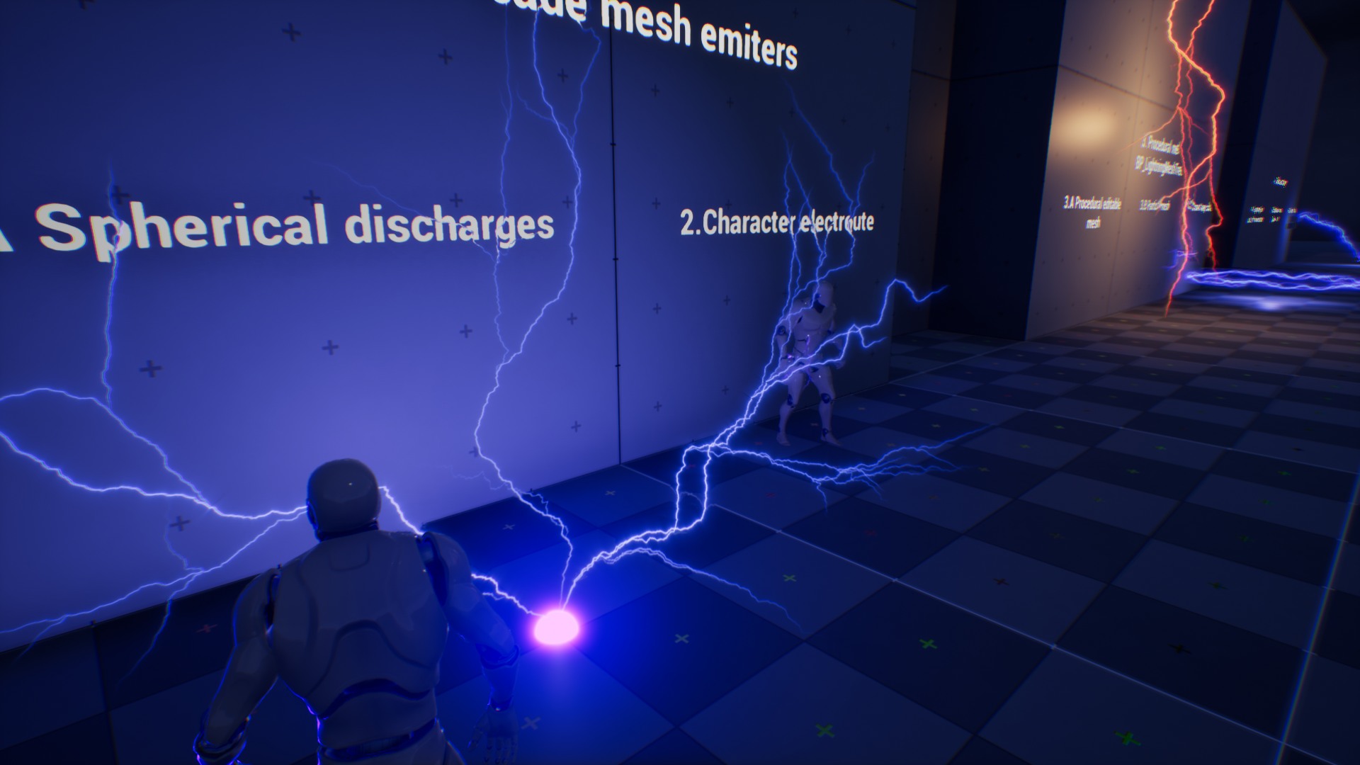
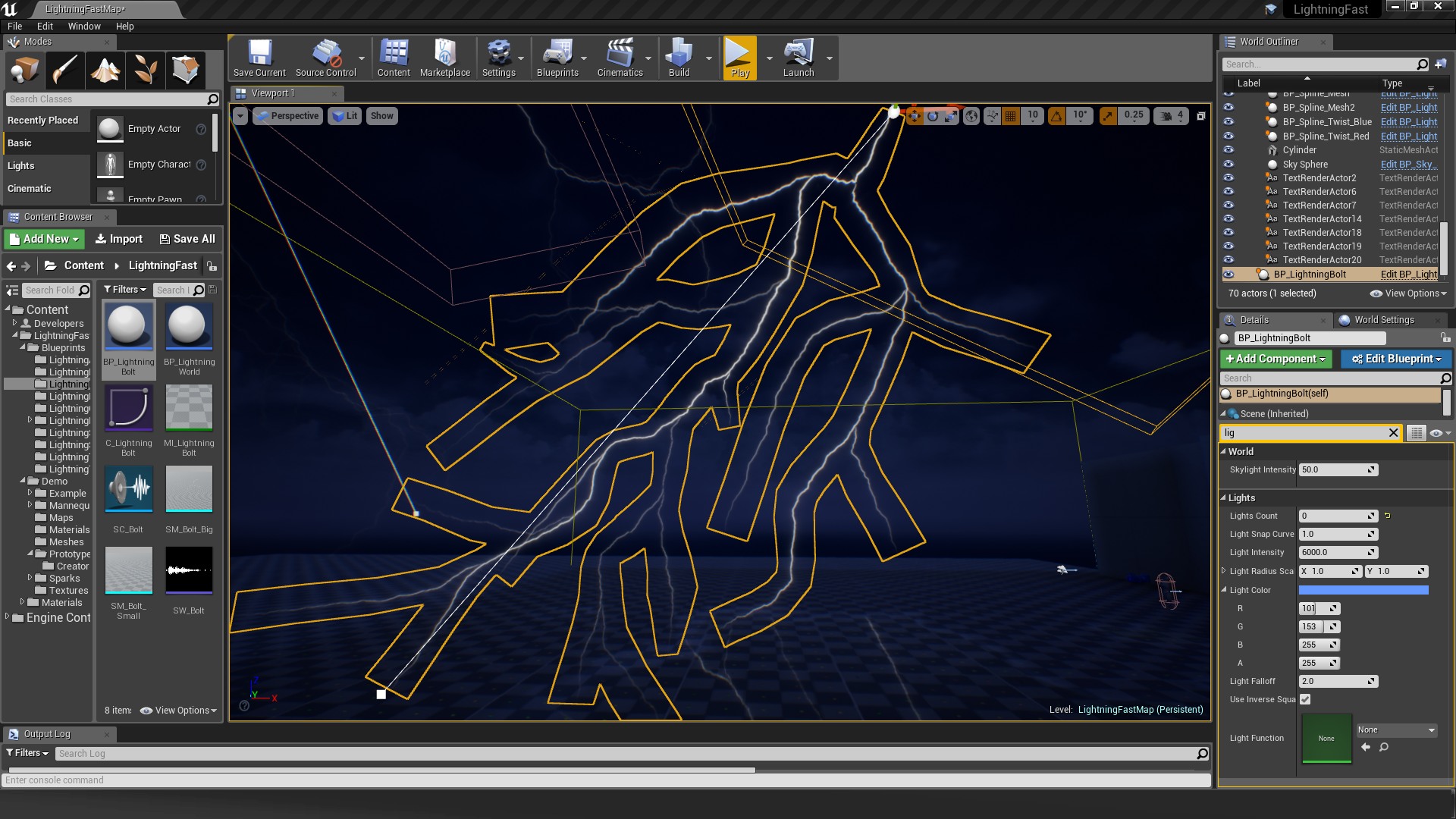
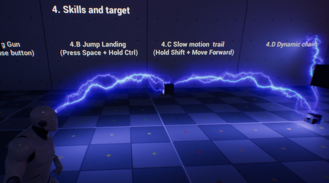
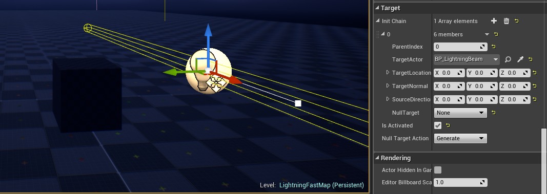
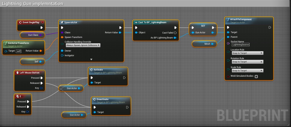
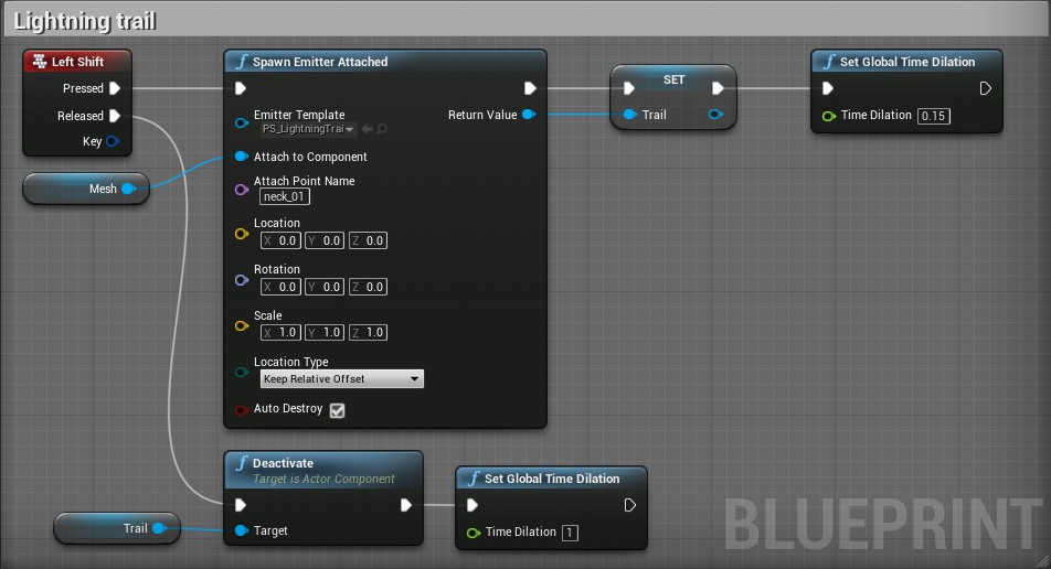
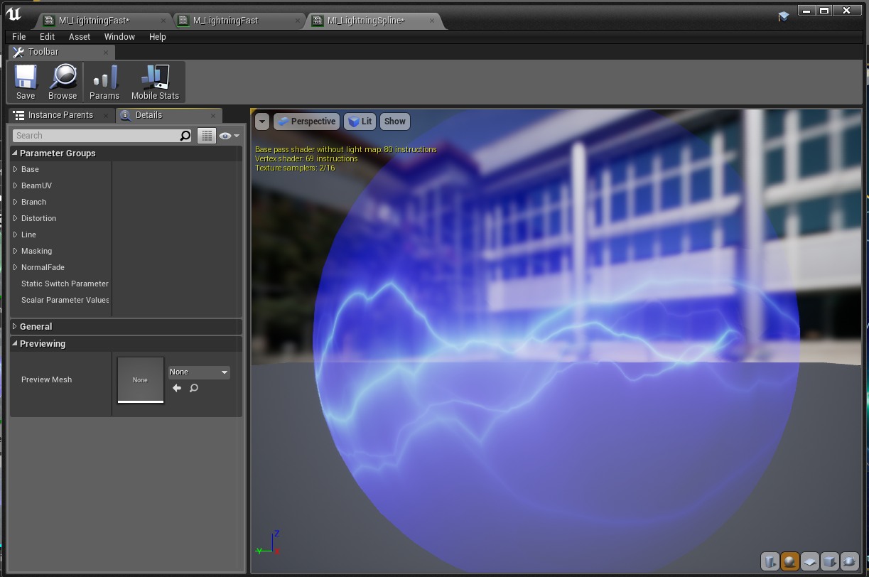
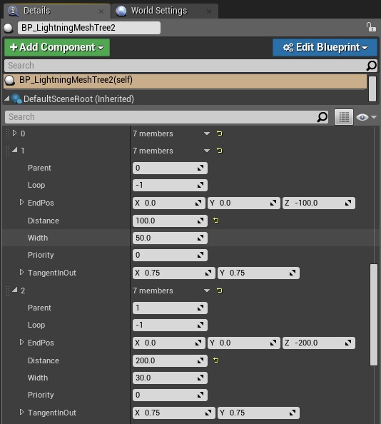 Lightning Fast package contains mesh editor BP_LightningMesh that allows the creation of unique lighting meshes. Drag and drop blueprint on scene Blueprints/LightningMesh/BP_LightningMesh to start creating a lightning mesh.