
Introduction
- Category: Materials
- Update: 1.0 (06-04-2019)
- Unreal Engine: 4.18-4.22
- Platforms: VR, PC, Console, HTML
Description
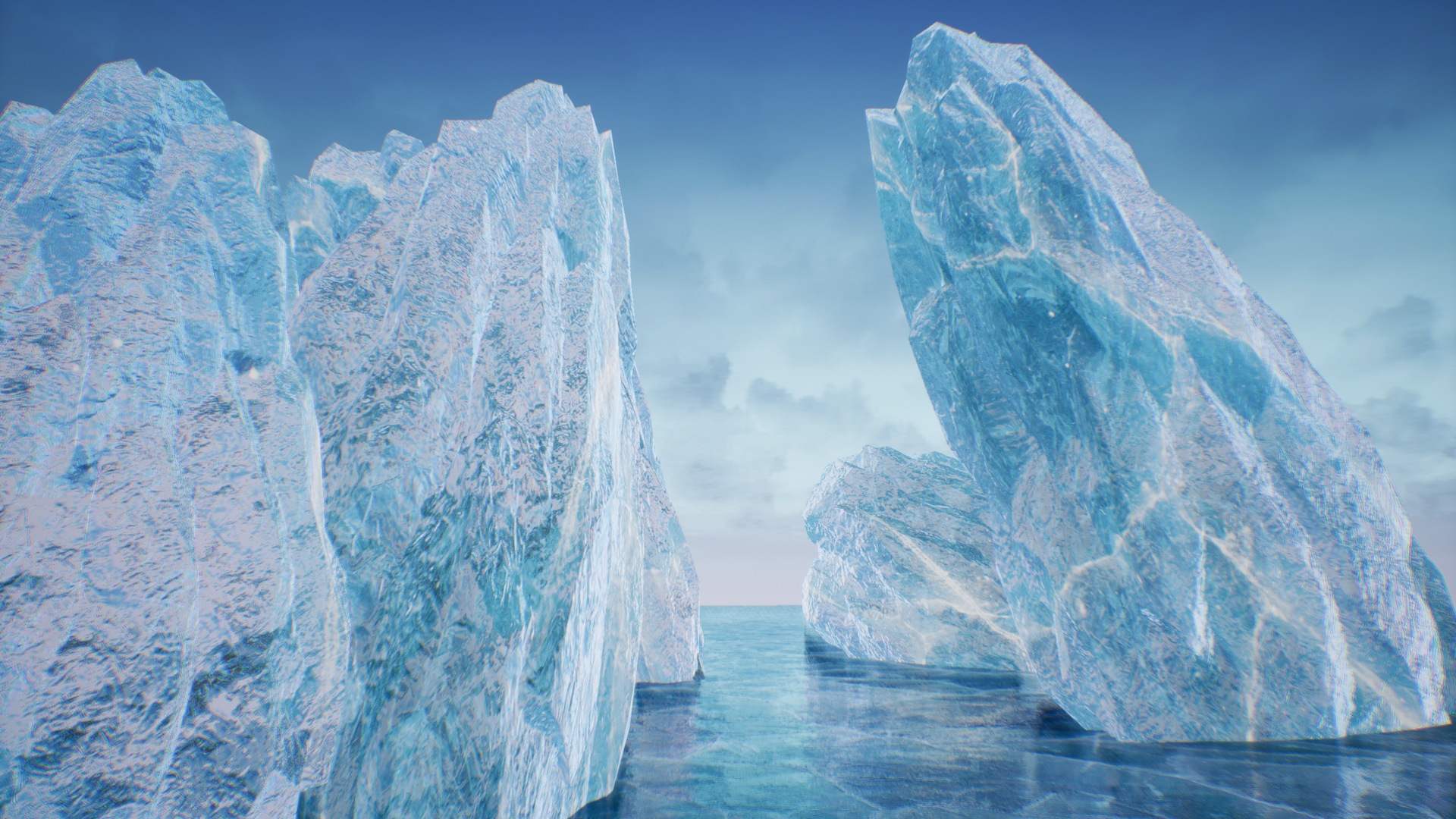
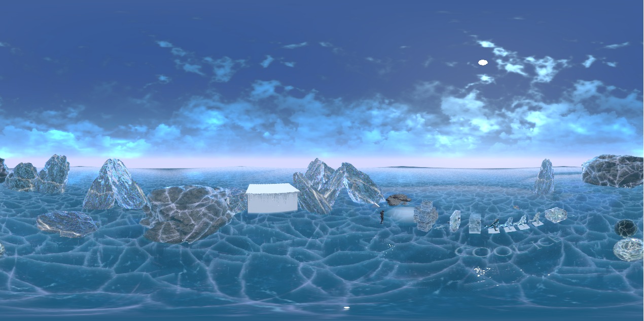
Ice Cool is an advanced master material prepared especially to create multiple types of ice like ground ice, ice cubes, icebergs, crystals, glass, and icicles. The translucent material option is a great solution for improving your level by storytelling on cold Arctic maps. Designed and optimized specially for Mobile, Virtual Reality, and stylized PC/Console games.
Features
- Customization options. Over 200 parameters to make it look cool. Additionally, Over 50 switches allow controlling efficiency-quality trade-offs.
- Uses the NEW FAST cracks rendering method. Implementation of the new cheap iterative technique of parallax for rendering deep cracks based on Signed Distance Field Textures. Thanks to using the SDF result effect stays clean and smooth even on closeups with using only 7 texture reads! (5 times faster than other methods).
- Supports multiple types of refraction. Supported cube map with box projection mapping/screen color/built-in refraction pin.
- Advanced translucency options. Translucency supports depth-fading fog for a better quality of covering the objects inside the ice.
- Subsurface scattering and custom lighting. Useful for more advanced users to better fit the ice into the scene.
- Extended reflection mode. The system supports pre-rendered cube map reflections mapped on meshes using box projection mapping and spherical mapping. This method is very fast even on translucent materials.
- Icy vertex offsets. Material supports configurable Vertex displacement for Icicles.
- Masked dithering. You can configure the system to use translucent material only where you need it and dither the opaque material around the wholes.
- Animated dust. A configurable dust map with refraction noise makes the material look even deeper and real.
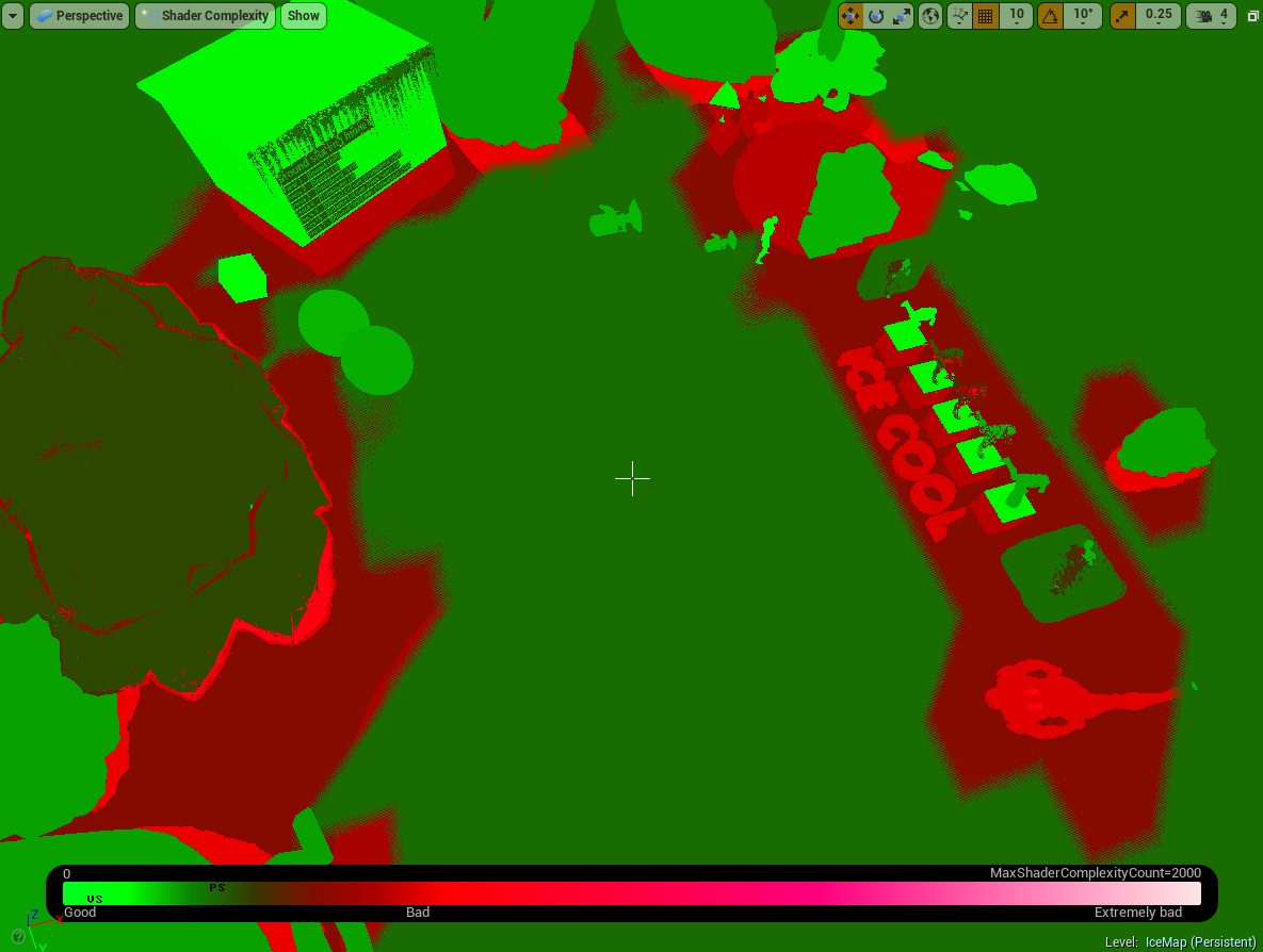
- Efficient and GPU friendly. Uses between 90-210 instructions depending on the number of features enabled can be used on VR and even mobile.
- Extra tools. The system includes additional tools for generating new Signed Distance Fields and environment cube maps.
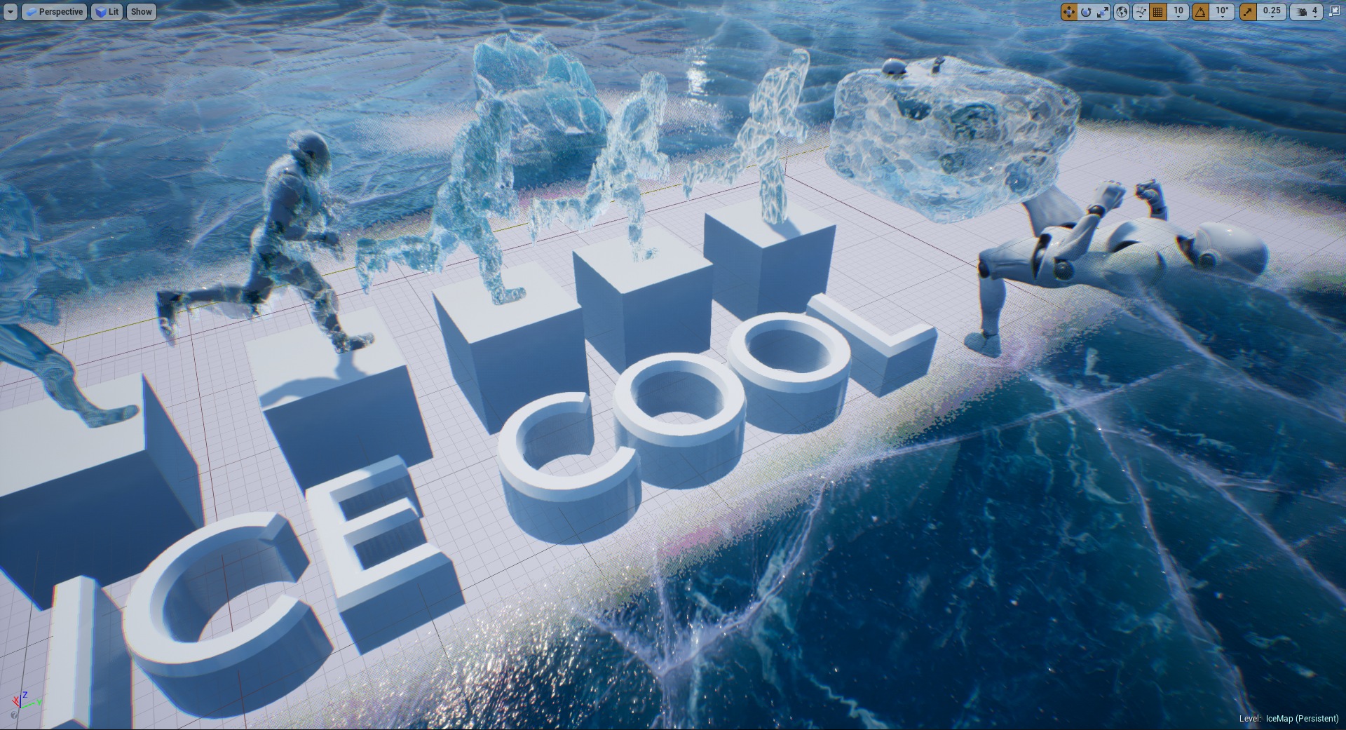
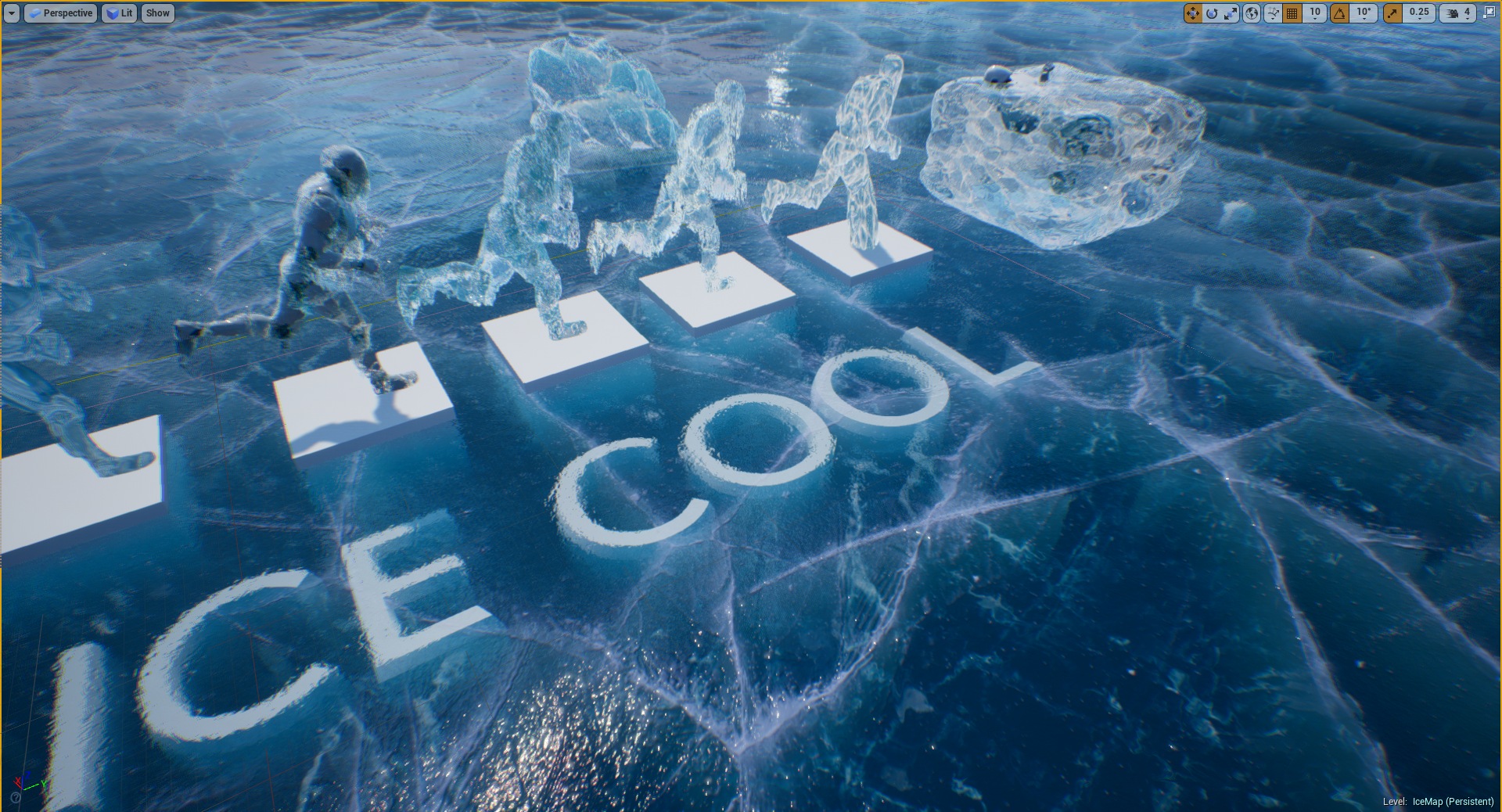
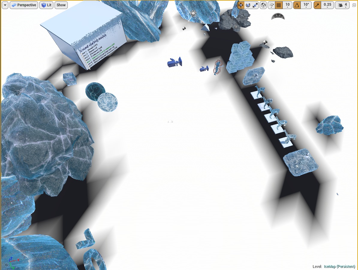
- Multiple useful examples. The package contains an example map with a showcase of multiple samples of using the material.
Gallery


Documentation
Get Started
Ice Cool is a pack based on a single advanced master material. The material is placed in the folder IceCool/Materials/M_IceCool. Every user has two ways of working with the package.
- Copy Material (Easy one) – Copy example material and modify the parameter to fit the requirements. You can check the example materials in the demo IceMap.
- Create Material (Hard one) – Create a material instance from master material and set material parameters from scratch.
This documentation covers both approaches to creating cool ice material.
It is good practice to create New Folder where the materials created using Ice Cool package will be stored. Try to not modify or add any content do the Ice Cool package it will protect your project from problems after downloading the new updates of the package.
Copy existing material
Ice Cool package contains a demo folder with multiple examples of materials of ice prepared for the specific conditions that can be copied to your project. All examples of ice materials are stored in the Demo/ExampleMaterils folder.
- Cracked ground
- Half-translucent ice cubes
- Opaque icebergs
- Translucent icicles
- Ice coating
- Select material that you want to use in your game
- Click the right button on the material and choose duplicate (if you want to copy) or create a material instance (if you want to extend the material and modify parameters).
- Move the newly created material into your project folder.
Cracked ground
The cracked ground is the most advanced use of the Ice Cool package. This material is prepared to be used as a ground. The UV coordinates of ice texture are calculated in the world space so the material can be used regardless of mapping or ground size. There are multiple types of this material prepared to fulfill the requirements of quality and platform type that the game targets. The demo allows seeing differences between every type of material by pressing keys 1-7 on the example map.
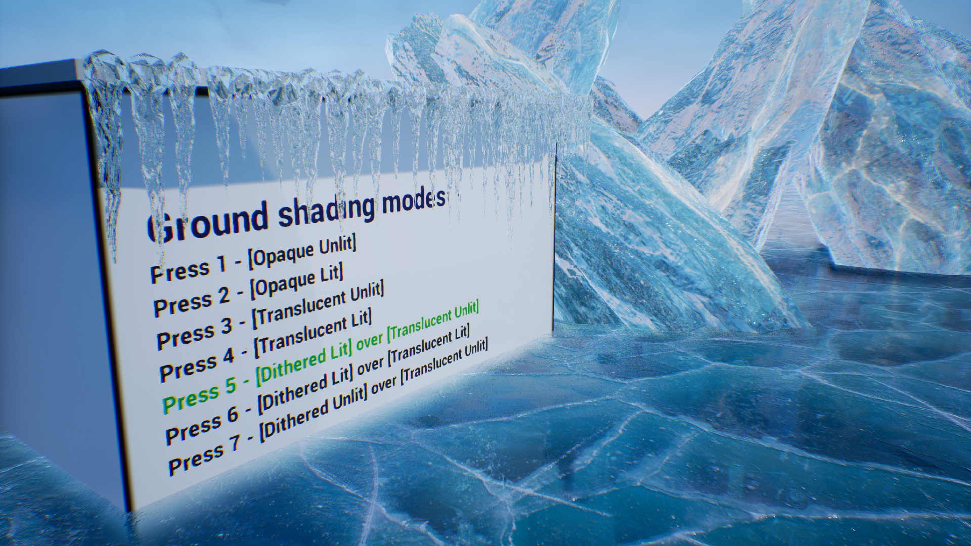
| Material Type | Lighting | Reflections | Platform |
| Opaque Unlit | Material parameters | Cubemap | All |
| Opaque Lit | Build-in UE4 | Reflection Captures | All |
| Translucent Unlit | Material parameters | Cubemap | All |
| Translucent Lit | Build-in UE4 | Cubemap | PC |
| Dithered Lit + Translucent Unlit | Mixed | Cubemap near the camera. | PC |
| Dithered Lit + Translucent Lit | Build-in UE4. Best quality. | Cubemap near the camera. | PC |
| Dithered Unlit + Translucent Unlit | Material parameters | Cubemap | PC |
Half translucent cubes
Half translucent means that this type of ice is a combination of two meshes opaque and translucent.
- Inside layer (MI_IceBlockBigInside) Opaque mesh is rendered from inside of the geometry (normal inverted front face culling)
- Outside layer (MI_IceBlockBigOutside) Translucent mesh is rendered traditionally as a layer over the ice.
This kind of material is useful when you want to put some meshes into an ice cube and achieve good effects of refraction. The mesh will be rendered between the inside and outside layers.
Opaque icebergs
Very efficient good-looking looking opaque material useful for icebergs that use refraction based on external cubemap.
Translucent icicles
This material type was prepared especially for creating icicles hanging from a roof. The additional layer of animated dirt makes it look wet.
Create new material
If you are not interested in using predefined materials of ice then there is always the harder path to follow. You can remove all demo content and create the material instance from scratch.
- Find the base material IceCool/Materials
- Duplicate the MI_IceCool or create a material instance from M_IceCool.
- Rename newly created material and move it to the Ice Materials folder in your project.
- Material is ready to use from now on.
I’m not recommending you this method. It requires a lot of knowledge about the ice material and this documentation does not cover all details yet.
Reflection
The reflection effect is based on pre-rendered cube maps. A detailed explanation of how to create a cube map for ice can be found in the Tools/Cubemap Rendering chapter. Ice materials support two types of reflection mapping. Spherical reflections and box projection mapping.
- Spherical mapping – Very fast but inaccurate. Works out of the box.
- Box projection mapping – Very accurate in box-shaped rooms. Requires additional room-size pieces of information in the materials.
| Box projection mapping | |
| UseBoxProjection | Allows using box projection mapping. If disabled then the system uses standard spherical cube-map projection. |
| ReflectionBoxExtend | half the size of the room cached in the reflection map. |
| ReflectionBoxPosition | Position the camera where the reflection was cached. |
| UseReflectionBoxLocal | Forces system to use reflection box capture in local space of actor position. Useful when the mesh is connected to the same actor as the reflection capture component. |
Other reflection parameters:
|
Reflections |
|
| ReflectionColor | The color of the reflection allows for adjusting the cube map to underwater conditions. An alpha channel represents the power of Fresnel. |
| ReflectionTexture | Prebaked cube map reflection texture should be cached in a place where the glass is rendered. |
| Use Shlick Reflection | Enables physical-based Shlicks Fresnel calculations. Otherwise use fast simplified dot(camera, normal) Fresnel. |
| UseReflectionBoxLocal | When true then ReflectionBoxPosition will be added to the actor position. |
Refraction
The package supports multiple advanced types of refraction. Each type of refraction is useful for a different scenario.
- Build-in UE4 refraction
- Screen color refraction
- Opaque cube map refraction
Fast dithered layers
The dithered material is the composition of two meshes with the top layer implemented as dither translucent. That combination allows using the slow translucent materials only where it is needed and increases the quality of lighting and reflections at low cost by using the opaque material over the translucent.
- The top mesh layer uses opaque dithered material that has high-quality reflections and lighting implemented by Epic.
- The bottom mesh layer uses a layer of translucent material that is covered by the top layer using a dithered transition.
It’s good practice to use bottom translucent layer only where it is needed and cut invisible parts of this mesh to increase a performance by lowering the geometry overdraw.
Dithered material can be masked by a vertex color alpha channel painted in the vertex paint mode. This functionality is active only when the UseDitheringVertexAlpha option in the top opaque material is active.
| Material parameter | |
| Use Dithering Distance | Use dithering in distance from the camera. |
| Use Dithering Vertex Alpha | Use masking of the dithering by vertex alpha. |
| Use Dithering Per Vertex | Calculate the distance for dithering per vertex to lower the shader complexity. It can cause some quality problems when using low-density meshes. |
| Dithering Border | Dithering distance border. |
| Dithering Smooth | Dithering border smoothing. |
Parallax cracks
Advanced algorithm for rendering parallax cracks uses the information about the distance from the crack to render a very efficient and smooth effect in only 6-8 texture reads. In comparison to other algorithms, it is over 6 times faster and looks much better on closeups.
| Material parameter | |
| Use Cracks | Whether the effect of cracks should be used in the material. The cost of this effect is noticeable (about 30-40) instruction so it’s good to enable this flag only when intended to use effect. |
| Cracks SDF Texture | A signed Distance Field texture was used to generate the effect. A detailed description of preparing SDF textures can be found in the chapter “Signed Distance Fields Rendering”. |
| Cracks Color | A bottom color of the effect of the cracks. |
| Cracks Color Light | A top color of the effect of the cracks. |
| Cracks Depth Iteration | The number of iterations used to calculate the effect. Best results can be achieved in between 5-10 iterations. It’s worth minimizing this value for optimization. |
| Cracks Depth Step Size | Step size per iteration |
| Cracks Depth Scattering | Depth scattering scale. |
| Cracks Depth Scale | Depth intensity scale. |
| Cracks Depth Smooth | Smoothing of the effect. It should be lowered when there are a lot of holes in the cracks. |
| Cracks Distortion | Distortion of cracks based on normal. |
| Cracks Width | Width of the effect. It should be between 0.93 and 1.0. |
| Cracks Height | Height of the effect. |
Dust
Ice Cool package supports a deep layer of animated dust.
| Dust parameters | |
| Use Dust | Whether the dust should be used in the material. |
| Dust Color | The color multiplier for the dust texture |
| Dust depth shift | An offset of the dust layer |
| Use Dust Layered | Whether to use the second layer of dust. |
| Dust Layer Between | Interpolation of layer rendered in between base layer and mesh surface. |
| Dust Texture | The texture is used as a dust layer. |
| Dust Texture UV Scale | UV coordinates (X, Y) and scale(Z, W) |
| Dust Texture UV Anim | UV animation speed per second (X, Y) |
| Use Dust World Space UV | Whether to calculate dust UV in world space or take it from UV0. |
| Use Dust Noise | Whether to distort the dust layer by noise texture. |
| Use Dust Noise Alpha | Whether to read distortion of UV dust layer from noise alpha. |
| Dust Noise Texture | Dust noise texture source. |
| Dust Noise Scale | Dust noise texture UV scale. |
| Use Dust Noise World Space UV | Whether to calculate dust noise UV in world space or take it from UV0. |
Coating
The coating effect extrudes the mesh in a direction created from normal and gravity vectors. The coating effect is useful for covering geometry with ice with additional icicles hanging from a mesh.
| Coating parameters | |
| Use Coating | Whether the coating effect should be enabled |
| Coating Offset | Channels RGB represents the direction of gravity length of this vector represents force. Channel A is a coating size in the direction of normal. |
| Coating Normal Distortion | Changes noisy distortion in a normal direction. |
| UseCoatingNoise | Whether to use noise function to calculate random offsets. |
| UseCoatingNoiseSkin | When true noise will be calculated using Skin vertex position, false force system to use texture UV. |
| CoatingNoiseScale | Noise irregularity |
| UseCoatingTexture | Changes noisy distortion in a normal direction. |
| CoatingTextureUVScale | Coating texture UV modyfikator. |
| CoatingTexture | The texture is used for the coating effect. |
Animated coating
Since update 1.1 Ice Cool supports an animated coating effect that can be useful during freezing meshes.
Multiple types of coating growing animation:
- SPHERE – UseCoatingSphereAnimation = true. Coating is growing inside the sphere described by (CoatingSphere.rgb – location, CoatingSphere.a – radius)
- PLANE – UseCoatingPlaneAnimatio = true. Coating is growing inside the sphere described by (CoatingPlane.rgb – normal, CoatingPlane.a – plane offset)
- FLAT – time based evenly growing. Growing controlled by CoatingFlatBlend float (0 – no coating, 1- full coating )
| Coating Animation | |
| UseCoatingAnimation | Whether the coating animation effect should be used. |
| CoatingAnimationTime | Flat coating animation effect blends between no coating and full coating. Should be modified externally by blueprints. |
| CoatingAnimTranslucent | Speed of showing the coating effect in the translucency channel. |
| CoatingAnimType | Displacement mode type. 0 – first type, 1 – second type (just check the difference in showing icicles and shell) |
| CoatingShapeDistanceBlend | The soft blend between no coating effect and full coating is used in a plane and sphere mode. |
| UseCoatingPlaneAnimation |
The coating is growing inside the sphere described by the Coating Plane |
| CoatingPlane | CoatingPlane.rgb – normal, CoatingPlane.a – plane offset. Should be modified externally by blueprints. |
| UseCoatingSphereAnimation | The coating is growing inside the sphere described by the Coating Sphere |
| CoatingSphere | CoatingSphere.rgb – location, CoatingSphere.a – radius radius. Should be modified externally by blueprints. |
| UseCoatingShapeLocalPosition | Use the local space position of the vertex during sphere/plane calculations. |
| UseCoatingDebugAnimation | Show example debug animations. Disable when you want to animate manually in the blueprint by using material parameters. |
Tools
Ice Cool package contains additional tools that can help to use the full potential of the material system.
Cubemap reflections rendering
Materials use cube maps for simulating the reflection and refraction of opaque materials. Those cube maps can be created using the BP_CaptureCubeMap blueprint.
- Place Blueprints/BP_SceneCaptureCube on your map and set up a proper position to capture the scene (the center of the room would be great).
- Open the IceCool/Tools folder and select the render target (RT_SceneCapture).
- Click right on the RT_SceneCapture and select “create static texture” The newly created texture is ready to use.
- Set the reflection texture cube map to the material parameter called ReflectionTexture.
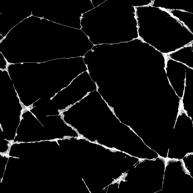
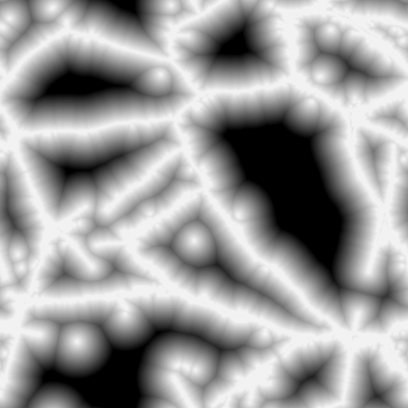
Signed Distance Fields rendering
A signed Distance Field is an image where each pixel contains the distance to the nearest point on the boundary. An additional sign of distance allows determining if the pixel is inside or outside rendered shape. SDF image that looks like a gradient can be loaded from a file or generated by mathematical functions called Signed Distance Functions.
Short description of how to create the SDF texture:
- Place the BP_SignedDistanceFiled on the map.
- Setup parameters.
Source Texture The texture that will be used for generating the SDF. Search Width The width of the search is the distance in pixels. W*W is the number of iterations per pixel. Big numbers can crash the program. Texture Size Resolution of the texture. - Click Generate to update the render target.
- Click right on the RT_SceneCapture and select “create static texture” The newly created texture is ready to use.
- Use the texture as the CracksSDFTexture parameter.